80S-20贴片机.pdf - 第219页
SIPLACE 80 S-20/F4 Service Manual 7 Components Table Edition 03/97 7.3 Components Table Power Supply 7 - 17 7.3 Com ponents T able Power Suppl y DANGER QQQ Before you start w ork on th e comp onents tab le powe r suppl y…
7 Components Table SIPLACE 80 S-20/F4 Service Manual
7.2 Fault Characteristics Edition 03/97
7 - 16

SIPLACE 80 S-20/F4 Service Manual 7 Components Table
Edition 03/97 7.3 Components Table Power Supply
7 - 17
7.3 Components Table Power Supply
DANGER QQQ
Before you start work on the components table power supply, the components changeover table must be dis-
connected from the main power supply (main power plug, on the right-hand side of the machine base).
Please note, with all work in the machine base interior and in particular on the components table power supply
the stricter VDE 0113 safety regulations apply.
7.3.1 Tools and Spare Parts Required
Auxiliary Measuring and Test Equipment
● Ohmmeter
Spare Parts
● Miniature fuse 5x20/T3,16AT, from item no. 00304938-01
● Cable for components table interface Y558-W1, from item no. 00300380-06
● Cable for transformer power supply of components table Y545-W1, from item no. 00300379-03
NOTE:
With error message "Communication with table interrupted" the fuse F1 at transformer T1 could be defective.
Carry out preliminary fault location with the aid of Section 7.2 ’Fault Characteristics’.
Details of the components table power supply will be found in the Overview section, the corresponding circuit
diagrams in the current circuit diagrams folder: Plan 1710460-Y0928-...-L-.../ -Y0558-..-L-... / -Y0545-...-L-..
7.3.2 Replacing Fuse F1
● Select "Abort placement" to return all picked-up components.
DANGER QQQ
Switch off the machine at the main switch and disconnect it from the main power supply.
● Undo the plug connections of the components changeover table at the machine base on the right beside
the components changeover table (mains and interface connector X37 and if applicable the pneumatic
connection).
● Open the protective covers and pull cover at the components loading point upwards and away.
7 Components Table SIPLACE 80 S-20/F4 Service Manual
7.3 Components Table Power Supply Edition 03/97
7 - 18
● Slide the placement head by hand over the board conveyor (see CAUTION note in Section 7.2 ’Fault Char-
acteristics’).
● Release the clamping lever and lift and using a lift truck move the components changeover table including
fitted feeder modules carefully out of the machine as described in the User Manual.
● Make sure that the mains plug of the components table is pulled out!
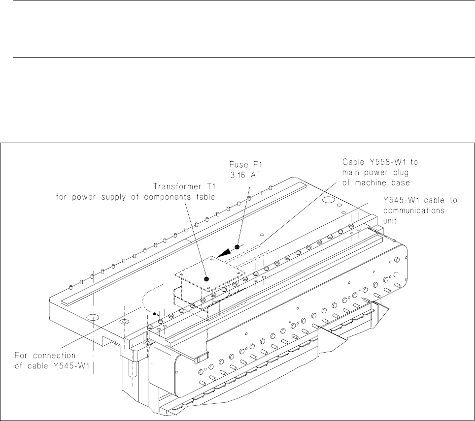
● Unscrew and remove the fuse F1 at the transformer T1 (see Fig. 7.3.1).
– If the fuse is defective, first, where possible, remove the cause of the problem, which should be looked
for on the output side of the transformer:
If necessary, remove the communications unit (see Section 7.5) and use the meter at the 5-pin plug
(cable of power supply communications unit) to see whether there is a short circuit in the cable or in
the transformer winding. Please note the following NOTE!
– If you can correct short circuit in another way, replace the fuse, rating 3,16 AT.
NOTE
The transformer T1 and / or the cables Y558-W1 and Y545-W1 at the transformer (see Fig. 7.3.1) will be
replaced only by the SMD Service department of Siemens AG.
● Install the components changeover table back in the machine in the reverse sequence of operations to
removal as described above. Make sure the plug connections (mains plug and X37, and, if applicable,
pneumatic connection) are firmly seated.
● Switch the machine on and start the placement sequence.
Fig. 7.3.1 Components table power supply: checking and replacing the fuse