80S-20贴片机.pdf - 第271页
SIPLACE 80S-20/F4 Service Manual 8 IC Head Edition 01/97 8.3 Servicing Work on the Z Axis 8 - 9 6HUY LFLQJ: RUNRQWK H=$[LV 7 RROV(TXLSPHQW DQG&RQVXPDEO HV 6S DUH3DUW V 5HS ODFHWK H7 …
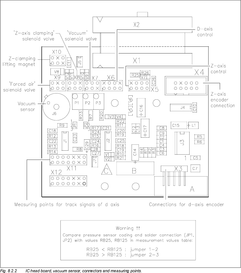
8 IC Head SIPLACE 80S-20/F4 Service Manual
8.2 Structure and Functional Groups of the IC Head Edition 01/97
8 - 8

SIPLACE 80S-20/F4 Service Manual 8 IC Head
Edition 01/97 8.3 Servicing Work on the Z Axis
8 - 9
6HUYLFLQJ:RUNRQWKH=$[LV
7RROV(TXLSPHQWDQG&RQVXPDEOHV
6SDUH3DUWV
5HSODFHWKH7RRWKHG%HOW
See item 7 in Fig. 8.3.1 page 8 - 12
● Loosen the synchronizing disc to slacken off the toothed belt.
● Replace the toothed belt.
● Adjust the tension of the toothed belt until the belt tension measuring device displays a frequency of
190Hz ± 5Hz.
● Check the zero point correction value and the axis servo setting.
)URPLWHPQXPEHU
Hexagon socket screw key, set
Open-ended spanner, size 13
Mount for sleeve removal 00318297-01
BRECO belt tension measuring device, complete 00326015-01
Feeler gauges 0.5 mm - 1.0 mm
SITEST program
Adjusting Instructions
Loctite 241 screw adhesive 02101037-01
)URPLWHPQXPEHU
Synchroflex 6T2/220 toothed belt 00304069-01
Motor for z axis 00306385-02
Spring steel sheet (nozzle support) 00304037-05
End position BERO 3RG4/6.5 mm/sn = 1.5 mm/1S 00306432-01
IC head sleeve, complete 00310555-01

8 IC Head SIPLACE 80S-20/F4 Service Manual
8.3 Servicing Work on the Z Axis Edition 01/97
8 - 10
5HSODFH0RWRU:LWK=$[LV7DFKR
7RGLVDVVHPEOH
● Slacken off the toothed belt as described in section 8.3.3, page 8 - 9 and pull it away.
● Detach all electrical cables to and from the motor.
● Loosen the hexagon socket head screw holding the motor in place.
● Remove the motor.
7RUHDVVHPEOH
● Position the new motor so that the end face of the motor ends flush with the head housing.
● Fix the motor in place with the hexagon socket head screw.
● Replace all electrical cables to and from the motor.
● Attach the driving toothed belt.
● Tighten the toothed belt as described in section 8.3.3, page 8 - 9.
● Check the zero point correction value and the axis servo setting (see section 8.3.9, page 8 - 14).
5HSODFH1R]]OH6XSSRUW6SULQJ6WHHO6KHHWRQWKH6OHHYH
See item 2, Fig. 8.3.1 page 8 - 12
PLEASE NOTE
If the spring plate of the sleeve mount is broken, the entire mount must be replaced.
● Fix the mount for the sleeve removal to the lower end of the sleeve.
● Unscrew the star.
● Lift the damaged spring steel sheet away from the star and fit the new plate. The alignment is determined
by the centering pin. The three beads in the spring steel sheet should point downwards.
● Remove any residues of glue from the thread.
● Apply a little LOCTITE 241 adhesive to the thread.
● Firmly bolt the star to the new spring steel sheet.
WARNING
Do not move the z axis unless the clamping device has been deactivated, since this could damage the
sleeve clamping device.
● Check the zero point correction of the d axis.