80S-20贴片机.pdf - 第153页
SIPLACE 80S -20/F4/F4-6/F5 Service Manual 5 Gantries Edition 09/99 5.7 Exchanging the X-/Y-Trailing Cable 5 - 45 ● If th e protec tive hos e is too l ong, mo ve the bot tom end of the rib bon cabl e until the end of the …

5 Gantries SIPLACE 80S-20/F4/F4-6/F5 Service Manual
5.7 Exchanging the X-/Y-Trailing Cable Edition 09/99
5 - 44
● Mount the Y-strain relief device exactly parallel to the Y-gantry rail (2 screws, size 3 Allen wrench:
see Fig. 5.7.10).
CAUTION O
If the outer edges of the strain relief device are not exactly parallel to the Y-gantry rail, the protective hose
will move at an angle and will be damaged.
l Run the ribbon cables to the gantry board and make the plug-in connections:
● Lay the cables into the cable hanger from the side (see Fig. 5.7.8).
● Pull the cables down from the top enough so that they are lying completely flat next to the Y-gantry
rail.
● Remove the Masking tape from the connectors.
● Make the plug-in connections to the gantry board with the correct allocation (bottom cable -> connec-
tion to bottom plug-in connector).
● Put 3 ties back on the ribbon cable package (see Fig. 5.7.6).
l Connect the pneumatic hoses to the air distributor and fasten the hoses in place:
● Adjust the total length of the 7-tube hose at the bottom (right-angle cut).
● Run the 7-tube pneumatic hose to the air distributor next to the Y-gantry rail (see Fig. 5.7.9).
● Separate the hoses, starting at the point at which they emerge from the protective hose to the air dis-
tributor or remove any Masking tape on the ends of the hoses.
● Connect the hoses to the air distributor.
- Hoses No. 1 and 2 have to allocated correctly at the air distributor.
- To do so, refer to Fig. 5.7.18 and the diagram of the pneumatic system (S-20 or F4 / F5) from the
current folder of circuit diagrams.
● Fasten the Y-trailing cable in the correct position on the Y-trailing cable hanger:
● Bolt the bottom U-bracket of the cable supply chain to the “Y-strain relief device" (2 screws, size 3
Allen wrench: see Fig. 5.7.10).
● Check whether the cover band is on the outside of the cable supply chain and is undamaged. If not,
mount a new cover band (Item No.: see Section 5.7.2) on the entire length of the cable supply chain.
The cover band is placed under the top and bottom U-bracket.
● Insert the remaining 2 pins into the trailing cable hanger and push them to stop on the other side in
the slots (see Fig. 5.7.11). This fastens the Y-trailing cable in place.
● Run the Y-trailing cable along the cable supply chain such that it is just against it (see Fig. 5.7.21).
Pay attention to the following NOTE.
NOTE
The protective hose (with cable/hose package) is not to push against the cable supply chain.
There is not to be a visible space between chain and hose.
The protective hose (with cable/hose package) should be just touching the cable supply chain at both
gantry end positions.
SIPLACE 80S-20/F4/F4-6/F5 Service Manual 5 Gantries
Edition 09/99 5.7 Exchanging the X-/Y-Trailing Cable
5 - 45
● If the protective hose is too long, move the bottom end of the ribbon cable until the end of the hose
that is to be cut off is safely outside
the machine.
By doing so you ensure that no fabric fibers end up in the machine area during the subsequent
steps. Cut off the protective hose smooth and at right angles with sharp scissors. The end of the pro-
tective hose should not protrude over the Y-strain relief device.
● If the criteria in the above-mentioned NOTE are not observed, proceed as follows:
- If there is a space at the loop of the cable supply chain, loosen the fasteners on the Y-trailing
cable hanger again, pull the trailing cable on the protective hose up slightly and refasten it in that
position (see above).
- If the protective hose is pressing against the loop of the cable supply chain / touching too much,
try changing the position of the cable supply chain’s bottom U-bracket in the slots. If this does not
suffice, remove the Y-strain relief device again and move the trailing cable (protective hose with
contents)
an appropriate amount and put the reversing pin back in. Tighten the screws holding the Y-strain
relief device.
● Manually push the Y-gantry into the min. and max. travel position. In each case, make certain that the
above condition is fulfilled (see Fig. 5.7.21 -> Check 2 !).
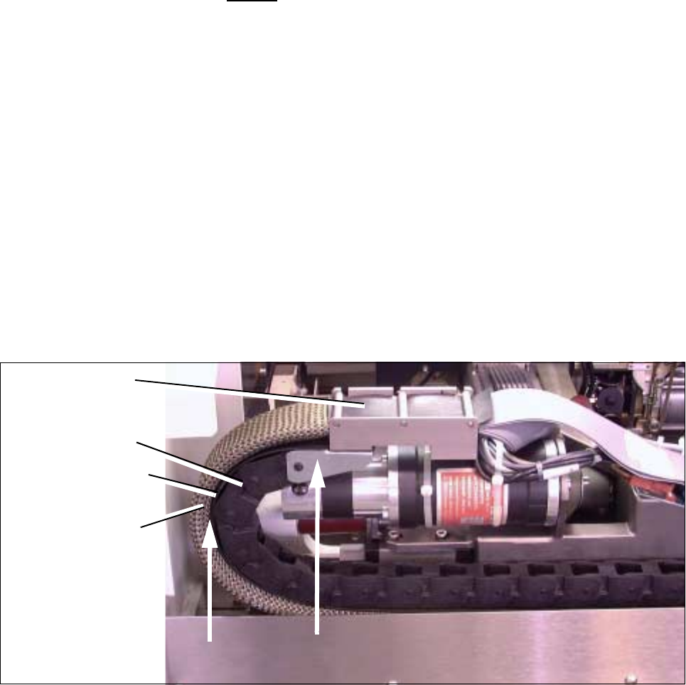
Fig. 5.7.21 Resetting and Checking the Correct Distance from “Protective Hose to Cable Supply Chain”,
Checking the correct assembly of U-bracket (Example for F4/F5)
● Attach the plug-in connector of the 2 ribbon cables on the top to the “Large Axis” conversion board. Check
to ensure that the plug-in connectors are securely seated.
● Install the cover over the “Large Axis” conversion board (3 screws, size 2 Allen wrench). Perform the
"Final Steps".
Y-trailing cable
completely
Cable supply chain
bolted in placet
Cover band
inserted
Protective hose
Check 2 !
assembled
Check 1 !
5 Gantries SIPLACE 80S-20/F4/F4-6/F5 Service Manual
5.7 Exchanging the X-/Y-Trailing Cable Edition 09/99
5 - 46
5.7.8 Final Steps
● Install the cover over the revolver head (4 or 5 screws, size 2 Allen wrench: see Fig. 5.7.14).
● Carry out a visual inspection:
- Is the cable supply chain mounted correct (wide U-bracket must be at top, see Fig. 5.7.21 ->
Check 1 !) ?
- Is the bend an the transition from Y-gantry to the X-gantry properly executed (see Fig. 5.7.20) ?
- Is the cover band between the cable supply chain and the protective hose ?
- Is the protective hose over the outer radius of the cable supply chain neither too loose nor too
tight ?
- Are the “Y-strain relief device" and the cable train hanger (Y-axis) installed exactly parallel to the Y-
gantry rail ?
- Are the pneumatic hoses correctly allocated on the placement head and connected to the air dis-
tributor next to the Y-gantry ?
- Is the ribbon cable allocation to the connectors of the gantry board correct ?
Compare the ID markings on the cables and the board.
● Place the side guard next to the machine and plug the cable lug of the grounding cable onto the connec-
tor on the inside (see Fig. 5.7.5 -> 8).
● Install the side guard, initially attaching it with the four M6 screws that are one under the other (Size 5 Allen
wrench, see Fig. 5.7.5).
● Install the protective door on the component feeding and fasten it with the 2 remainig screws M6 on the
front of the side guard.
● Place the machine base doors into their hinges.
● Place the buffer bracket onto the centering pins and bolt the bracket on (1 screw, size 6 Allen wrench: see
Fig. 5.7.1 -> 8).
● Bolt on the cover plate above the side guard (4 - 5 screws, size 3 Allen wrench: see Fig. 5.7.5).
● Move the component changeover table/carriage back into the machine or, in the case of the F4/F5, put the
exchangeable (stationary) component table back in.
● Set up the stationary component in accordance with the specifications for set-up optimization.
● Where applicable, move the WPC into the machine.
● Install the plug-in connectors (for power supply and interface) for the component table (1 or 2) and the
WPC.
● Conduct a visual check to ensure that all empty tape ends in the empty-tape duct are conducted down
correctly.
● Remove all tools and equipment from the machine.
● At the main switch of the machine, turn the compressed air back on at the compressed air unit.
● Start the placement sequence.
q