80S-20贴片机.pdf - 第289页
SIPLACE 80S-20/F4 Service Manual 8 IC Head Edition 01/97 8.6 Measure Nozzle Changer 8 - 27 0HDVXUH 1R]]OH&KDQJHU 7 RROV(TXLSPHQW 'HWHUPLQ H;<&RRUGLQ DWHVRI WKH 1R]]O H*DUDJHV ● …
8 IC Head SIPLACE 80S-20/F4 Service Manual
8.5 Servicing Work on the Pneumatic System Edition 01/97
8 - 26
SIPLACE 80S-20/F4 Service Manual 8 IC Head
Edition 01/97 8.6 Measure Nozzle Changer
8 - 27
0HDVXUH1R]]OH&KDQJHU
7RROV(TXLSPHQW
'HWHUPLQH;<&RRUGLQDWHVRIWKH1R]]OH*DUDJHV
● Select the following menu sequence from the SITEST program:
Functions ↵ Nozzle changer ↵ Nozzle changer IC head ↵ Calibrate nozzle changer complete
'HWHUPLQH1R]]OH3LFN8S$QJOH
The nozzle pick-up angle is the angle at which the nozzle is removed from the garage.
● Connect the test box as described in the Adjusting Instructions.
● Place a nozzle on the nozzle support (spring steel sheet).
● Deactivate the dr axis.
● Manually turn the sleeve until the nozzle can be moved into the garage.
● Read the corresponding dr axis value on the test box.
● Use a DOS editor to enter this value.
PLEASE NOTE
It is generally sufficient to determine the value for one nozzle and then to use this value for the other noz-
zles.
The values in the test program for ’pick-up at d pos. or ’lock in place at d pos.‘ are used only to pick-up or
set down the nozzles correctly. They are not saved.
'HWHUPLQH3LFN8S+HLJKW
● Select the following menu sequence from the SITEST program:
Functions ↵ Nozzle changer ↵ Nozzle changer IC head ↵ Pick-up or return nozzle. The correct pick-up
height is determined by picking up and returning the nozzle.
)URPLWHPQXPEHU
SITEST program V ≥ 203.000
Nozzle removal tool 00311448-01
Test box
Adjusting Instructions
8 IC Head SIPLACE 80S-20/F4 Service Manual
8.6 Measure Nozzle Changer Edition 01/97
8 - 28
,QVHUW1R]]OHLQWR1R]]OH&KDQJHU
● Manually insert the new or serviced nozzles in the correct order into the nozzle changer.
● Using the nozzle removal tool, turn each nozzle to the left in order to lock it in place in the nozzle changer.
● Select the station menu functions Gantry 1 ↵ Nozzle changer configuration to display the assignment and
check the desired and actual values of the assignment for consistency.
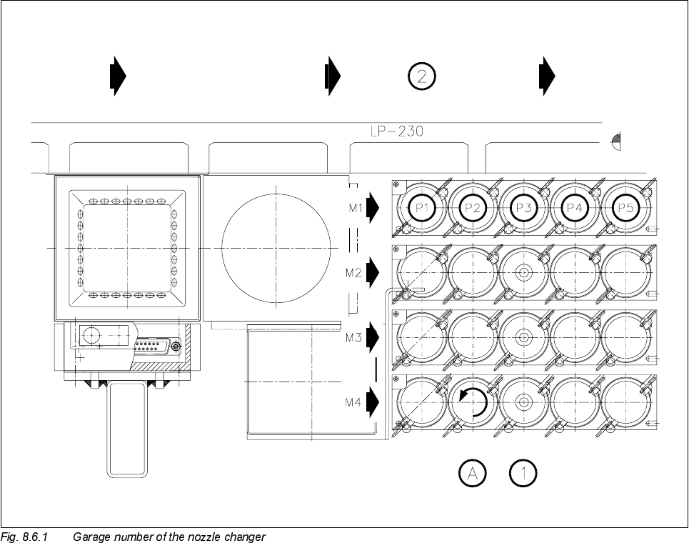
The general assignments are shown in the following diagram.
Key to Fig. 8.6.1
1 Nozzles 2 PCB transport direction
A Lock nozzle in place by turning to the left