80S-20贴片机.pdf - 第145页
SIPLACE 80S -20/F4/F4-6/F5 Service Manual 5 Gantries Edition 09/99 5.7 Exchanging the X-/Y-Trailing Cable 5 - 37 ● Loosening the pneumatic connections in the placement head area : Fig. 5.7.16 S-20 and F4/F5: Loosening Pn…
5 Gantries SIPLACE 80S-20/F4/F4-6/F5 Service Manual
5.7 Exchanging the X-/Y-Trailing Cable Edition 09/99
5 - 36
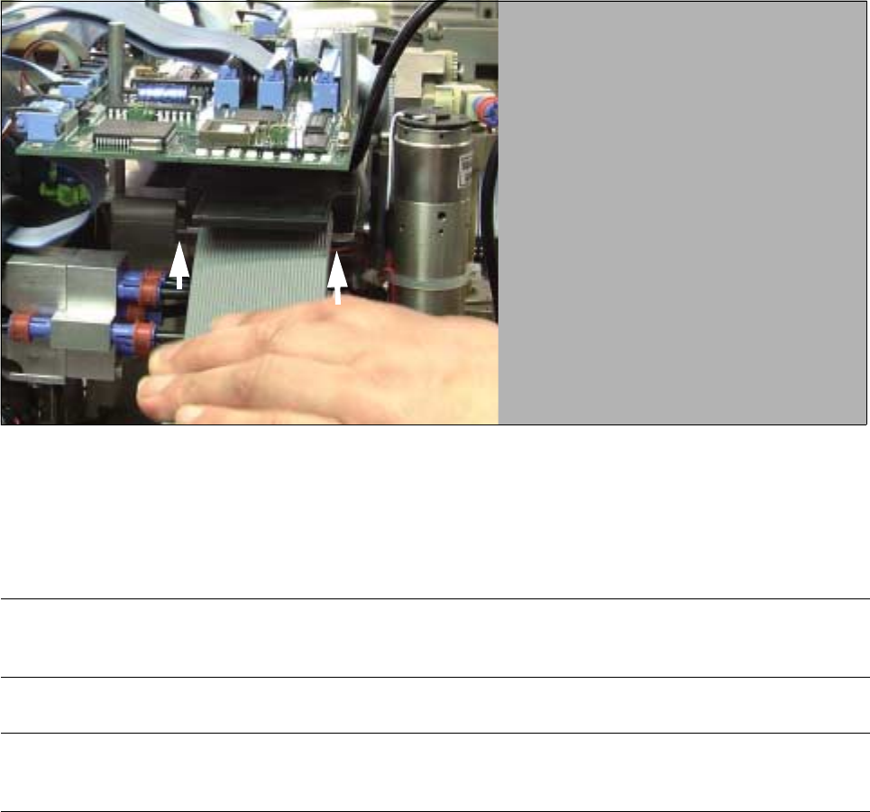
Fig. 5.7.15 Loosening the Counterstay (X-Cable Clamp) for X-Trailing Cable, Unplugging Ribbon Cable from Board
● Loosen the counterstay of the X-trailing cable under the “Small Axis” conversion board (loosen 2 screws
from the bottom, size 2.5 Allen wrench: see Fig. 5.7.15).
l Loosen plug-in connectors on the “Small Axis” conversion board (head board):
WARNING O O
Comply with regulations on ESDs (see Section 1 of this service manual.
NOTE
If only the 7-tube pneumatic hose is exchanged, skip the next 3 steps.
● Loosen the fasteners or the “Small Axis” conversion board at the studs (3 screws, size 2.5 Allen
wrench: see Fig. 5.7.2).
● Carefully tip the side of the board up and carefully pull all of the plug-in connectors of the X-trailing
cable off the bottom of the board.
● As a precautionary measure, fasten the board with at least one screw in the interim.
SIPLACE 80S-20/F4/F4-6/F5 Service Manual 5 Gantries
Edition 09/99 5.7 Exchanging the X-/Y-Trailing Cable
5 - 37
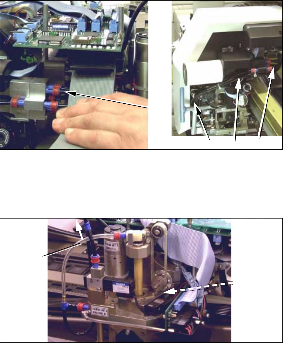
● Loosening the pneumatic connections in the placement head area:
Fig. 5.7.16 S-20 and F4/F5: Loosening Pneumatic Connections on the Revolver Head (or Reconnecting and Laying Them Correctly)
● S-20 and F5/F5: Loosen the 5 compressed air connections on the distributor block of the revolver
head (move red ring of quick-release fastener: see Fig. 5.7.16 -> 1).
On S-20, hoses 1 and 2 are not under pressure. For this reason they are run down the side of the
revolver head (see top right -> 2) and inserted behind the cross member (-> 3).
Loosen the 2 cable ties.
Fig. 5.7.17 F4/F5: Loosening the Pneumatic Connections on the IC Head (or Reconnecting Them Correctly)
● F4/F5: In addition to the connections on the revolver head (see Fig. 5.7.17), loosen the compressed
air connections on the IC head:
- 5.5 bar on the vacuum generator (Y-coupling: see Fig. 5.7.17) and
- 2.3 bar at solenoid valve for the Z-axis clamping unit (quick-release fastener: see Fig. 5.7.17).
1
F4 / F5
3
2
1
S-20
1
S-20
Connection to
pneumatic
system
2,3 bar
Connection to
pneumatic
vacuum
5,5 bar
system for
generator
(Y-connector)
for Z-axis
clamping unit

5 Gantries SIPLACE 80S-20/F4/F4-6/F5 Service Manual
5.7 Exchanging the X-/Y-Trailing Cable Edition 09/99
5 - 38
l Removing the entire trailing cable:
● Remove the entire ribbon cable package and the 7-tube pneumatic hose from the machine.
NOTE
If a single ribbon cable is faulty, all of the cables are removed because a complete, new set will be installed.
5.7.7 Installation
5.7.7.1 Installing New Protective Hose (without Exchanging the Cables/Hoses)
CAUTION O
A polyester hose is always used on machine option F5 DCA instead of the standard protective hose (see
Section 5.7.2).
If you are exchanging only the protective hose, proceed as follows:
● Place the separated hose ends (Y-gantry area, air distributor) flat side-by-side and wrap them with
Masking tape.
● Push the ribbon cable and pneumatic hoses carefully into the new protective hose, wrapped end first.
● Push the protective hose into the correct position relative to the Y-trailing cable hanger. Use the pressure
imprints on the existing pneumatic hose for orientation.
● Connect the hoses to the air distributor block next to the Y-gantry rail. Hoses No. 1 and 2 must be cor-
rectly assigned. To ensure this, refer to Fig. 5.7.18 and the relevant diagram of the pneumatic system (S-
20 and/or F4 / F5) from the current file of electric circuit diagrams
● Run the Y-trailing cable and fasten the protective hose to the Y-trailing cable hanger as described in Sec-
tion 5.7.7.5.