80S-20贴片机.pdf - 第453页
SIPLACE 80S-20/F4 Service Manual 13 6-Segment Revolver Head (8000) Edition 07/97 13.9 6x Nozzle Changer 13 - 39 6WHS VIRU,QVWDOOLQJWKH1R]]OH&KDQJHU&RQWURO%RDUG ● Introdu ce the contr ol boar d int…

13 6-Segment Revolver Head (8000) SIPLACE 80S-20/F4 Service Manual
13.9 6x Nozzle Changer Edition 07/97
13 - 38
5HSODFLQJWKH6SULQJ+RRNV
6SDUHSDUWV
– Spring hook, from item no. 00329170-01
7RROV
– Hexagon socket-head spanner, size 2.5
6WHSVIRUUHSODFLQJWKHVSULQJKRRN
● Remove the nozzle changer from the machine as described in section 13.9.1.
● Loosen the fixing screw on the spring hook and remove the spring hook
(see Fig. 13.9.2, item 1).
● Insert the new spring hook into the corresponding recess.
● Insert and tighten the fixing screw on the spring plate.
● Install the nozzle changer in the machine as described in section 13.9.2.
5HSODFLQJWKH1R]]OH&KDQJHU&RQWURO%RDUG
6SDUHSDUWV
– Nozzle changer control board, item no. 00317353-02
7RROV
– Hexagon socket-head spanner, size 2.5
6WHSVIRU5HPRYLQJWKH1R]]OH&KDQJHU&RQWURO%RDUG
● Remove the nozzle changer from the machine as described in section 13.9.1.
● Remove the connecting cable between the 5/2-way valve and plug X2 on the control board.
● Loosen the 4 M3x8 screws (see Fig. 13.9.3, item 6).
● Remove the control board by moving it towards the reject station (see Fig. 13.9.3,
item 4). When you do this, be careful not to damage the actuating plate of the light barrier.
PLEASE NOTE
Do not carry out any work on the actuating plate of the light barrier. This plate is set and coated at the factory.
SIPLACE 80S-20/F4 Service Manual 13 6-Segment Revolver Head (8000)
Edition 07/97 13.9 6x Nozzle Changer
13 - 39
6WHSVIRU,QVWDOOLQJWKH1R]]OH&KDQJHU&RQWURO%RDUG
● Introduce the control board into the nozzle changer from the reject station side.
● Screw down the board using the 4 M3x8 screws.
● Fit the connecting cable between the 5/2-way valve and plug X2 on the control board.
● Install the nozzle changer in the machine as described in section 13.9.2.
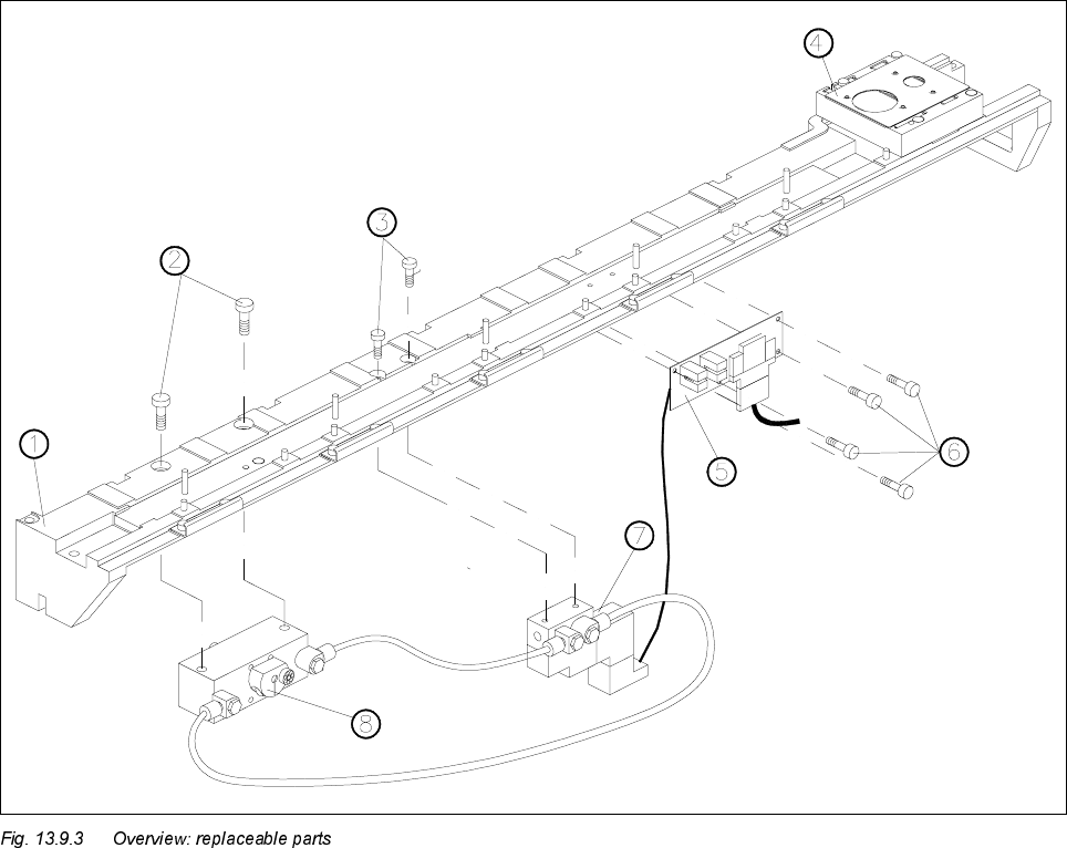
.H\WR)LJ
1Base
2 Encoder fixing screws
3 5/2-way valve fixing screws
4 Reject station
5 Nozzle changer control board
6 Control board fixing screws
75/2-way valve
8 Rotary drive
13 6-Segment Revolver Head (8000) SIPLACE 80S-20/F4 Service Manual
13.9 6x Nozzle Changer Edition 07/97
13 - 40
5HSODFLQJWKH:D\9DOYH
6SDUHSDUWV
– 5/2-way valve with base plate and cable, item no. 00317578-02
7RROV
– Hexagon socket-head spanners, size 3
6WHSVIRU5HPRYLQJWKH:D\9DOYH
● Remove the nozzle changer from the machine as described in section 13.9.1.
● Remove the connecting cable between the 5/2-way valve and plug X2 on the control board.
● Loosen the screws connecting the compressed air lines to the cylinder (see Fig. 13.9.3, item 7).
● Remove the compressed air hoses from the 5/2-way valve to the cylinder. When you do this, mark which
hose is assigned to which connection.
● Remove the middle magazine of the seven magazines as described in section 13.9.3.1.
● Loosen the 2 M4x16 screws (see Fig. 13.9.3, item 3).
● Remove the 5/2-way valve.
6WHSVIRU,QVWDOOLQJWKH:D\9DOYH
● Insert the 5/2-way valve in the nozzle changer.
● Fix the 5/2-way valve using the 2 M4x16 screws (see Fig. 13.9.3, item 3).
● Connect the compressed air hoses to the cylinder at the associated connections on the 5/2-way valve.
● Tighten the screws of the compressed air connections.
● Fit the connecting cable between the 5/2-way valve and plug X2 on the control board.
● Install the magazines you removed as described in section 13.9.3.2.
● Install the nozzle changer in the machine as described in section 13.9.2.