80S-20贴片机.pdf - 第425页
SIPLACE 80S-20/F4 Service Manual 13 6-Segment Revolver Head (8000) Edition 07/97 13.2 R eplacing the Valve Adjustment Dr ive for the Placement or Reject Circuits 13 - 11 13.2.3 Replacing the ’T urning Station Comp lete’ …

13 6-Segment Revolver Head (8000) SIPLACE 80S-20/F4 Service Manual
13.2 Replacing the Valve Adjustment Drive for the Placement or Reject Circuits Edition 07/97
13 - 10
13.2.2 Replacing the Valve Adjustment Drive for the Reject Circuit
Spare parts
Valve adjustment drive, from item no. 00319825S02
Test equipment
Distance gauge, from item no. 00325445-01
● Remove the complete placement head (see section 13.1.6).
● Undo the two recessed-head screws (M2 x 6) of the ribbon cable holders.
● Undo the hexagon socket screws (M3 x 10) and carefully pull away the valve adjustment drive (see Fig.
13.2.2).
● To re-install the valve adjustment drive, proceed in the reverse sequence of operations.
NOTE
When fitting the head, pay attention to the position of the two alignment pins.
When you re-install the ribbon cable holders make sure that you do not pinch the cables.
Adjustment Work
Carry out the adjustment work as described in section 13.2.1, page 13 - 8.
– If placement is slightly offset you will need to readjust the placement head (see the Sitest instructions).
SIPLACE 80S-20/F4 Service Manual 13 6-Segment Revolver Head (8000)
Edition 07/97 13.2 Replacing the Valve Adjustment Drive for the Placement or Reject Circuits
13 - 11
13.2.3 Replacing the ’Turning Station Complete’
Spare parts
– Turning station complete, from item no. 00319800S04
● Disconnect plug-in connections X10 and X12 from head board C0005.
● Undo the hexagon socket screw (M3 x 25) at the back of the placement head and carefully pull the turning
station towards the rear and out (see Fig. 13.2.2).
● To re-install the turning station, proceed in the reverse sequence of operations.
NOTE
When fitting the head, pay attention to the position of the two alignment pins.
– Please refer to the adjustment instructions for information on the procedure for checking the electrical
functions.
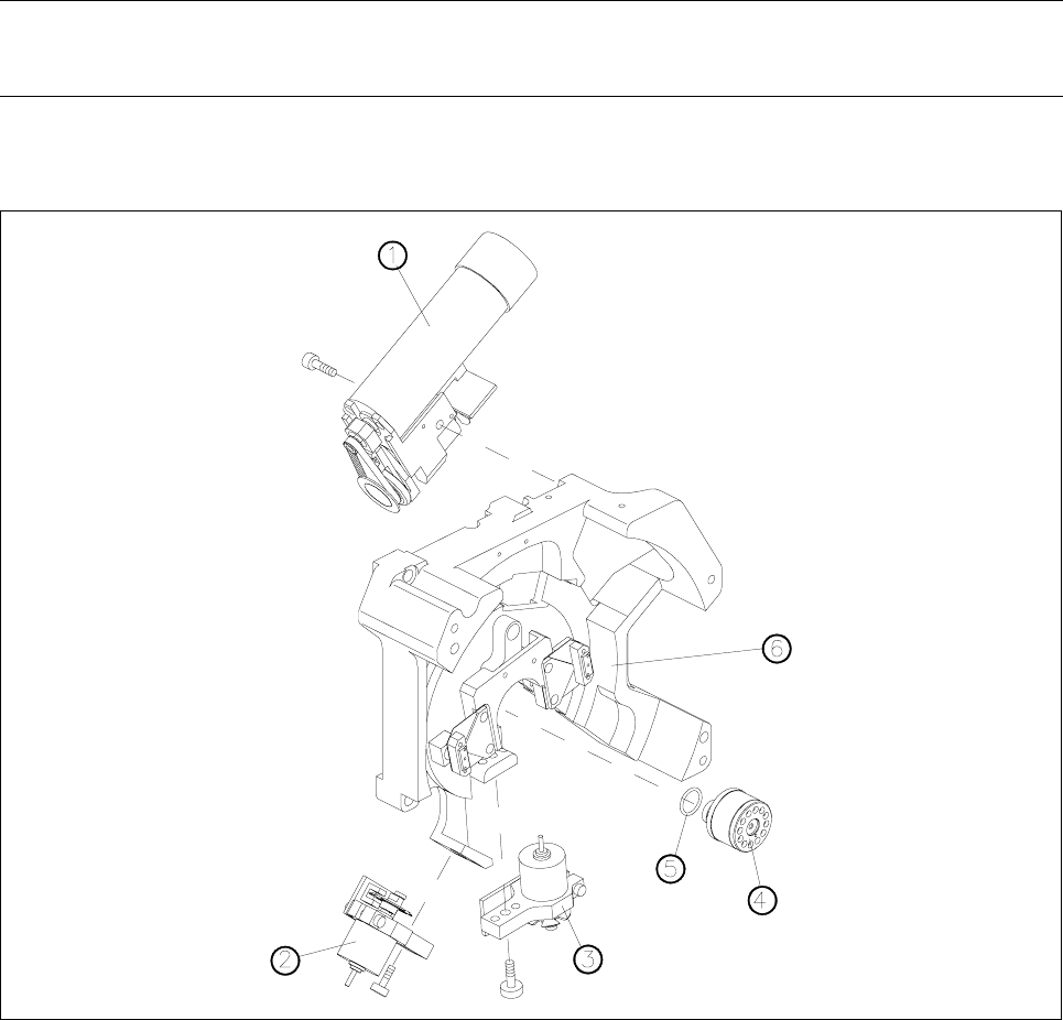
Fig. 13.2.2 Valve adjustment drives, turning station and distributor of the revolver head
1 Turning station
2 Reject circuit valve adjustment drive
3 Placement circuit valve adjustment drive
4 Distributor
5 O-ring
6 Back part of placement head
13 6-Segment Revolver Head (8000) SIPLACE 80S-20/F4 Service Manual
13.2 Replacing the Valve Adjustment Drive for the Placement or Reject Circuits Edition 07/97
13 - 12
13.2.4 Replacing the O-Ring
Spare parts
– O-ring 2x16 E 70B, from item no. 00320043S01
● Disconnect plug-in connections X10 and X12 from head board C0005.
● Undo the hexagon socket screw (M3 x 25) at the rear of the placement head and carefully pull the turning
station towards the rear and out (see Fig. 13.2.2).
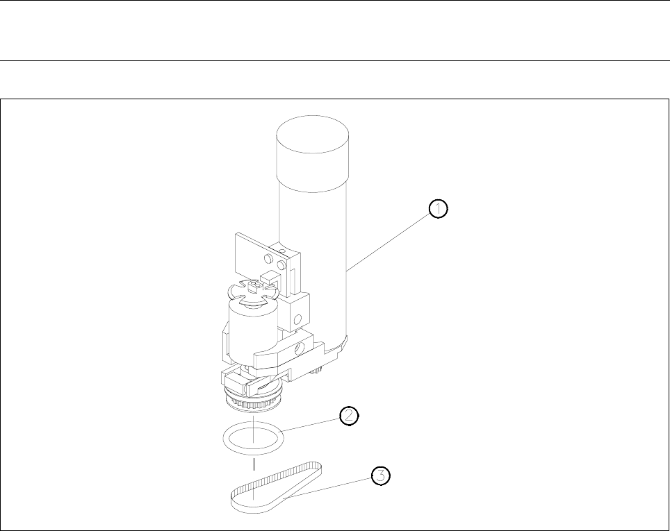
● Carefully remove the toothed belt from the motor pinion by simultaneously turning and pulling at the belt
(see Fig. 13.2.3).
● Now change the o-ring 2x16 (see Fig. 13.2.3).
● To re-install the turning station, proceed in the reverse sequence of operations.
NOTE
No adjustments of settings are required after changing the o-ring.
Fig. 13.2.3 Replacing the o-ring in the turning station
1 Turning station complete
2 O - ring 2x16
3 Toothed belt