80S-20贴片机.pdf - 第384页
12 Vision s ystems SIPLA CE 80S-20/F4/F5 Service Manual 12.6 Coplanarity Option Edition 09/99 12 - 32 ● Keeping the abo ve DAN GER text in min d, disman tle the empty-ta pe duct an d the c utter (old m odel) or the “pneu…

SIPLACE 80S-20/F4/F5 Service Manual 12 Vision systems
Edition 09/99 12.6 Coplanarity Option
12 - 31
3UHSDUDWRU\6WHSV
DANGER O O O
Turn the machine off and pull out the power plug for the machine.
Comply with all of the safety instructions in Section 12.6.1.
Observe the sequence of the steps in the job.
No bridging of safety equipment is to be performed.
Operating the coplanarity sensor (laser) outside the machine is not permitted.
WARNING O O
Always proceed in the following sequence when loosening or making the plug-in connections of the
changeover table and the wafflepack changer:
-> When pulling out the connections:
Always unplug the round connector first (power supply) of the component changeover table and/or
of the WPC and then, but only then, the square one (interface connector).
-> When restoring the connections:
Plug them back in in the reverse order (interface connector first and then the power supply connector).
● Press the "EMERGENCY OFF" button.
● Make certain that the key-operated switch is locked (position "0").
● Turn the machine off at the main switch and isolate the machine from the mains (see DANGER text,
above).
● If optional WPC or component changeover table (table 2) is installed (see Fig. 12.6.2):
● Unplug the two connectors on the left- or right-hand side of the machine base. Unplug the power sup-
ply connector first, then the interface connector. If necessary, move the WPC out of the machine.
● The subsequent steps depend on which component has to be exchanged:
"Sensor cable coplanarity" or sensor bracket:
First of all, continue the work as described starting in the next item.
- All other components: Continue the work as described in the pertinent section.
DANGER O O O
Comply with the safety instructions in the DANGER text in Section 12.6.1). There is danger of being crushed
or cut during the disassembly/assembly of the component table and the cutter.
You will require the pertinent service manual to disassemble the cutter (see Section 12.6.2 under "Documen-
tation").
● If a component table is installed, detach it and lift the table out of the machine with the assistance of a
2nd person.
12 Vision systems SIPLACE 80S-20/F4/F5 Service Manual
12.6 Coplanarity Option Edition 09/99
12 - 32
● Keeping the above DANGER text in mind, dismantle the empty-tape duct and the cutter (old model) or the
“pneumatic cutter”.
Proceed exactly as described in the pertinent SIPLACE Service Manual, under “Exchanging the
Cutter...".
-> Note in the case of the pneumatic cutter that the retaining bracket remains mounted.
● Continue the work by dismantling the sensor bracket (see Section 12.6.7) or the sensor cable (see Sec-
tion 12.6.8).
([FKDQJLQJWKH6HQVRU%UDFNHW

SIPLACE 80S-20/F4/F5 Service Manual 12 Vision systems
Edition 09/99 12.6 Coplanarity Option
12 - 33
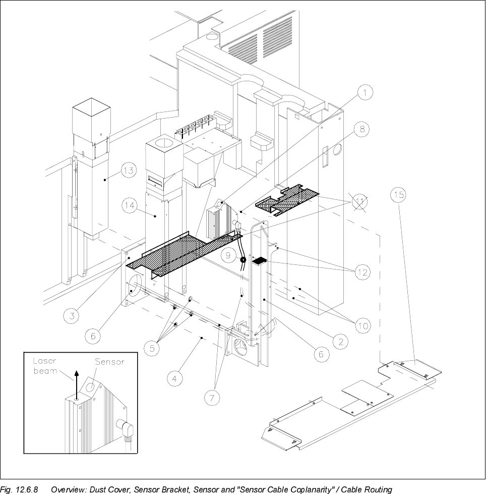
Key to Fig. 12.6.8 (look to your left):
1) Coplanarity sensor (laser) 2) Sensor bracket
3) Optional carrier for nozzle changer / flip-chip camera 4) Fasteners for sensor bracket
/ coplanarity sensor (remains mounted) Four M 6 x 20 socket-head cap screw
5) 8 ea. spacers 1 mm thick (2 spacers/screw) 6) Opening to run lines for coplanarity sensor
(only in case of dual conveyor, stationary side left and flip-chip camera
or right, inserted between bracket and optional carrier)
7) "Sensor cable coplanarity" 8) Fasteners for the sensor (laser)
three M 4 x 8 socket-head cap screws
9) 2 cable clips D = 6 mm 10) Fasteners for cable clips
two washers 4.3 DIN 125-A
two M 4 x 8 socket-head cap screws
11) Plastic dust cover *) over the conveyor trench 12) Contact surfaces for dust cover
Pos. 15 is always substituted
(see NOTE, below)
13) IC camera (remains mounted) 14) Flip-chip camera (remains mounted)
15) Metal dust cover
Fasteners: 3 or 4 ea washers 4,3 DIN 9021-A
3 or 4 ea M4 x 10 socket-head cap screws
NOTE in re *)
If a plastic dust cover is still installed (earlier model), this must be replaced by the metal dust cover (see Sec-
tion 12.6.10).
12.6.7.1 Disassembly: Sensor Bracket
● Precondition: The "Preparatory Steps" (Section 12.6.6) must be completely finished.
CAUTION O
During the following steps, make certain that you do not damage the cable (bracket has sharp corners) or
place any strain on the cables.
● Undo the fasteners holding the dust cover on the machine base under the PCB conveyor module (three or
four washers and M4 socket-hex cap screws) and remove the dust cover.
● If a metal cover is over the flip-chip camera, removed it so that you can unplug the cables.
● Unplug the ribbon cable (illumination control) and the video lead from the flip-chip camera (see Fig.
12.6.8).
● Carefully loosen any cable ties along the ribbon cable.
● Undo the screws fastening the sensor cable to the sensor bracket (2 cable clips, 2 washers, 2 M4 socket
hex cap screws: see Fig. 12.6.8 -> 10).