80S-20贴片机.pdf - 第437页
SIPLACE 80S-20/F4 Service Manual 13 6-Segment Revolver Head (8000) Edition 07/97 13.5 Z Axis Unit 13 - 23 13.5.5 Replacin g the ’Z Axis at B ottom’ S ensor PLEASE NOT E This wor k may o nly be c arried out by Sieme ns se…

13 6-Segment Revolver Head (8000) SIPLACE 80S-20/F4 Service Manual
13.5 Z Axis Unit Edition 07/97
13 - 22
13.5.4 Replacing the Toothed Belt for the Z Axis
PLEASE NOTE
This work may only be carried out by Siemens service technicians or by the customer’s appropriately trained
personnel.
Spare parts
Toothed belt Synchroflex 8AT3/201, from item no. 00320001-01
Test equipment
Belt tension measuring device TSM, from item no. 00326015-01
’Measure Belt Tension’ Instructions
Gauge for z axis, from item no. 00331308-01
● Undo the two hexagon socket screws (M2.5 x 8) and remove the toothed belt fastening (see Fig. 13.5.1,
Pos. 5).
● Undo the four hexagon socket screws (M3 x 5) of the motor mounting (see Fig. 13.5.1, Pos. 5).
● Position the new toothed belt over the motor pinion and the counterbearing.
ATTENTION ∆
!
∆
!
When you fit the toothed belt holder make sure that you position the belt correctly on the motor pinion.
● When installing, proceed in the reverse sequence of operations.
Adjustment work
● Remove the front part of the placement head (see section 13.1.6, page 13 - 6).
● Using the belt tension measuring device, check the belt tension in accordance with the values specified
below:
● Using your fingers lift the z axis a little and insert the z-axis gauge in pos. (A) in the bearing race
(see pos. 8, Fig. 13.5.1, page 13 - 24).
The z axis is located 0.3 mm above the bearing race.
● Adjust the upper stop (pos. 7) in a way, that it will touch the toothed belt fastening (pos. 5).
● Fit the front part of the placement head (see section 13.1.6, page 13 - 6).
● Determine the zero point correction value for the z axis (see section 13.5.3, page 13 - 21).
PLEASE NOTE
After installing the placement head, determine the star zero point correction as described in section 13.6.3.
Prior to continuous operation
frequency (Hz)
After continuous operation
frequency (Hz)
Z-axis toothed belt of
revolver head
185 ± 10 185 ± 10

SIPLACE 80S-20/F4 Service Manual 13 6-Segment Revolver Head (8000)
Edition 07/97 13.5 Z Axis Unit
13 - 23
13.5.5 Replacing the ’Z Axis at Bottom’ Sensor
PLEASE NOTE
This work may only be carried out by Siemens service technicians or by the customer’s appropriately trained
personnel.
Spare parts
Sensor ’Z-axis at bottom’, from item no. 00321524S03
Test equipment
Precision test pin, dia. 1.3
, from item no. 00326163-01
● Disconnect plug-in connection X11 from the distributor board.
● Undo the three hexagon socket screws (1 x M2 x 8 and 2 x M2 x 5) of the ribbon cable holders and remove
the ribbon cable.
● Undo the two slotted head screws (M1.6 x 4) and remove the ’Z axis at bottom’ sensor.
● Using the precision test pin set the lateral clearance between the light barrier and the nozzle ring to
1.3 mm.
● When re-installing, proceed in the reverse sequence of operations.
NOTE
Be careful when routing the ribbon cable.
13 6-Segment Revolver Head (8000) SIPLACE 80S-20/F4 Service Manual
13.5 Z Axis Unit Edition 07/97
13 - 24
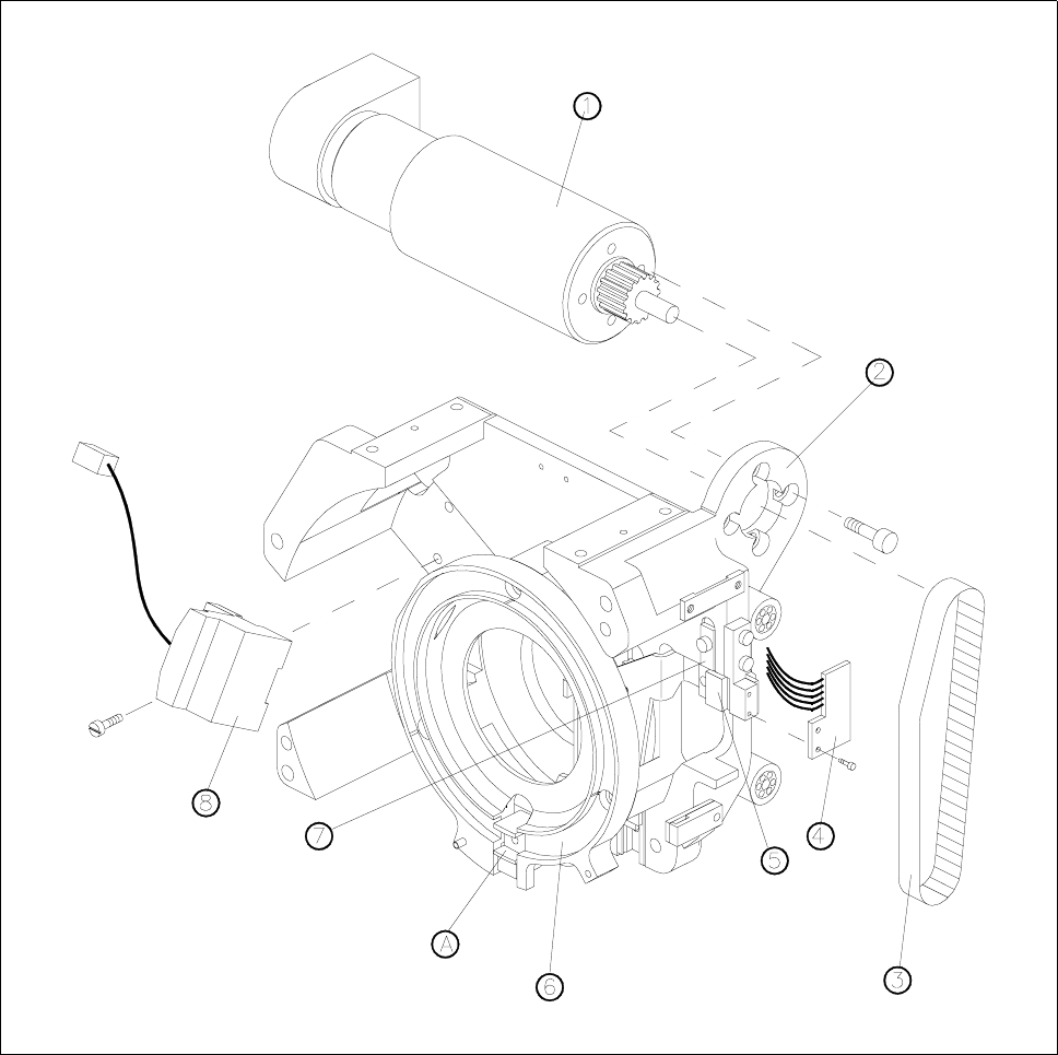
Fig. 13.5.1 Z-axis drive and sensor
1 Motor for z axis
2 Motor mounting
3 Toothed belt for z axis
4 ’Z axis at top’ sensor
5 Toothed belt fastening
6 Clamping ring
7 Upper stop for z axis
8 D-axis encoder
A Insert z-axis gauge here