80S-20贴片机.pdf - 第302页
9 12-Segment Revolver Head (10000) SIPLACE 80S-20/F4 Service Manual 9.1 12-Segment Revolver Head (10000) Edition 07/97 9 - 6 9.1.5 Removing the ’Cover complete’ ● Remove t he fiv e M3x5 hexa gon so cket scre ws for mo un…
SIPLACE 80S-20/F4 Service Manual 9 12-Segment Revolver Head (10000)
Edition 07/97 9.1 12-Segment Revolver Head (10000)
9 - 5
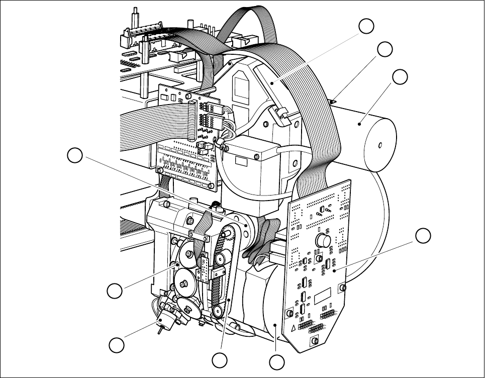
9.1.4 Structure of the 12-Segment Revolver Head (10000)
Fig. 9.1.1 Structure of the 12-segment revolver head
1 Reject circuit valve adjustment drive
2 Z axis toothed belt
3 Star motor
4 Distributor board
5Silencer
6 Vacuum board
7 Components camera
8 Z motor
9Star
008
008
8
7
2
1
9
5
4
3
6
9 12-Segment Revolver Head (10000) SIPLACE 80S-20/F4 Service Manual
9.1 12-Segment Revolver Head (10000) Edition 07/97
9 - 6
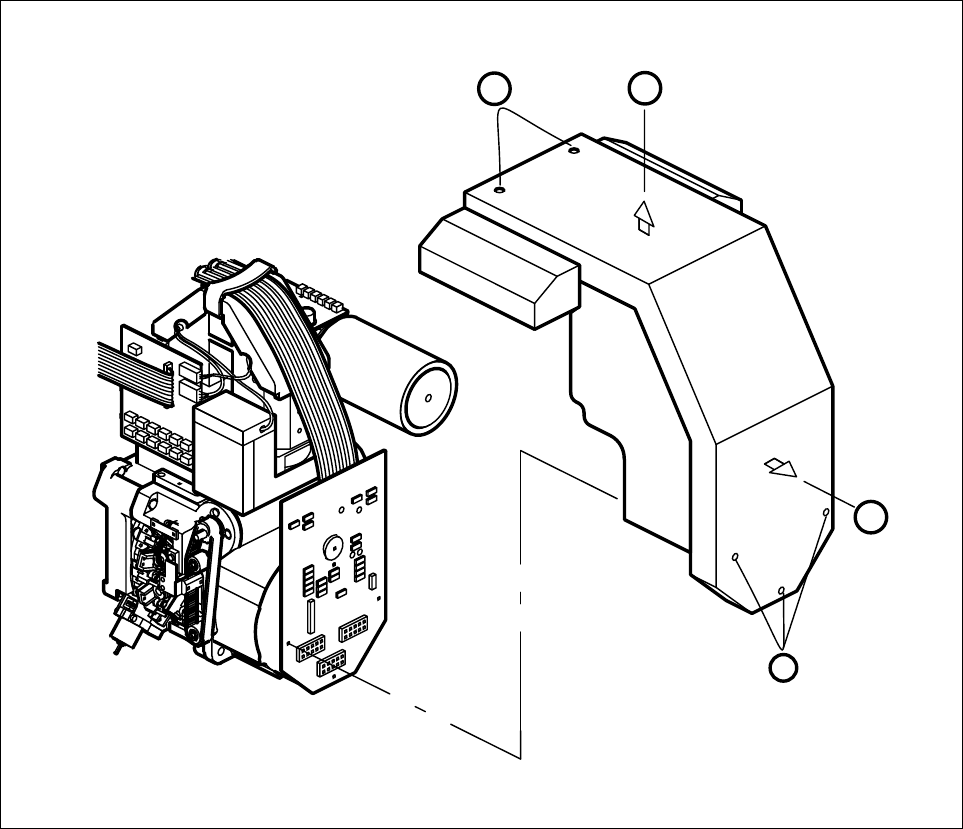
9.1.5 Removing the ’Cover complete’
● Remove the five M3x5 hexagon socket screws for mounting the cover (point A).
● Pull the cover a little towards you in horizontal direction (point B).
● Lift the cover up and away (point C).
● To install the cover, proceed in the reverse sequence of operations.
Fig. 9.1.2 Mounting and dismantling the cover
C
A
B
A
SIPLACE 80S-20/F4 Service Manual 9 12-Segment Revolver Head (10000)
Edition 07/97 9.1 12-Segment Revolver Head (10000)
9 - 7
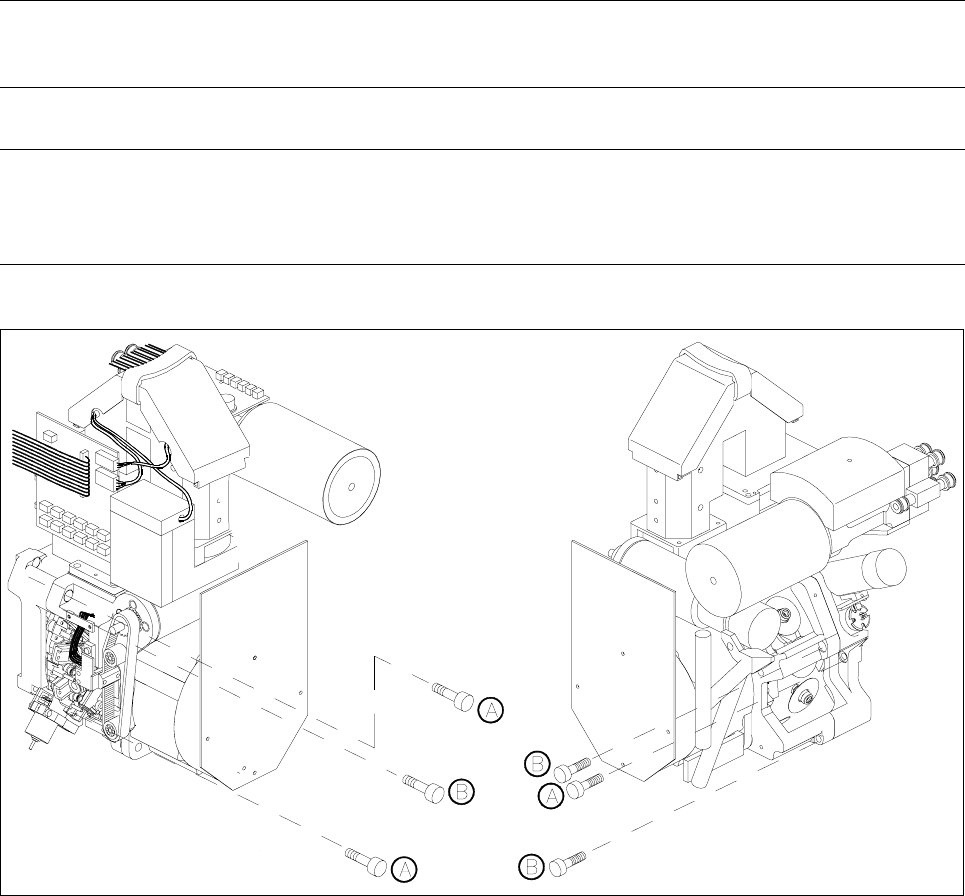
9.1.6 Removing the ’Placement Head Complete’
Spare parts
Revolver head 10000, from item no. 00321406S01
● Disconnect plug-in connections X3, X10, X12, X13, X14, X17, X18 and X19 from head board C0005.
● Disconnect all compressed air lines from the back of the vacuum generator.
● Undo the three hexagon socket screws (M4 x 16) (Refer to section 9.1.3 A) and carefully remove the
placement head from the placement machine.
– To install the head, proceed in the reverse sequence of operations.
NOTE
Pay attention to the keying of the plug when you reconnect the plug-in connections to head board C0005.
CAUTION ∆
!
Make sure you do not damage the cable or put tensile stress on the snap-in connections.
Fig. 9.1.3 Fastening screws of the 10000 placement head and the front part of the placement head
Key to Fig. 9.1.3
A Fastening screws of the placement head, complete
B Fastening screws for the front part of the placement head