80S-20贴片机.pdf - 第358页
12 Vision s ystems SIPLA CE 80S-20/F4/F5 Service Manual 12.1 Removing and ins talling the component change-over table E dition 09/99 12 - 6 4 5 3 1 2 4 5 6 8 7 A
SIPLACE 80S-20/F4/F5 Service Manual 12 Vision systems
Edition 09/99 12.1 Removing and installing the component change-over table
12 - 5
5HPRYLQJDQGLQVWDOOLQJWKHFRPSRQHQWFKDQJH
RYHUWDEOH
NOTE
If you wish to fit or remove the IC camera, the flip-chip camera or the coplanarity module you will have to
remove the component changeover table on the right-hand side of the table of the 80F machine.
7RROVUHTXLUHG
● Move the gantry to the lefthand side of the table.
DANGER
Switch the machine off and disconnect it from the main power supply.
NOTE
Disconnect the machine from the compressed air supply.
● Pull out the plug for the power supply to the components table ➁.
● Unplug the communications plug ➀.
● If necessary, undo the coupling for the compressed air supply to the components table ➂.
● Slide the lift truck beneath the components table (A).
● Undo the two hexagon socket screws which fasten the components table ➄.
● Open the horizontal tension jacks ➆.
● With the lift truck carefully raise the component changeover table until the centering pins ➇ emerge from
their holes.
● Now pull the component changeover table to the outside.
● Remove the waste tape chute of the cutting unit.
● When fitting, proceed in the reverse sequence of actions.
)URPLWHPQXPEHU
Set of hexagon socket wrenches
Lift truck for changeover table 00123141-01
12 Vision systems SIPLACE 80S-20/F4/F5 Service Manual
12.1 Removing and installing the component change-over table Edition 09/99
12 - 6
4
5
3
1
2
4
5
6
8
7
A

SIPLACE 80S-20/F4/F5 Service Manual 12 Vision systems
Edition 09/99 12.2 Replacing the IC vision camera and illumination control board (SIPLACE 80F)
12 - 7
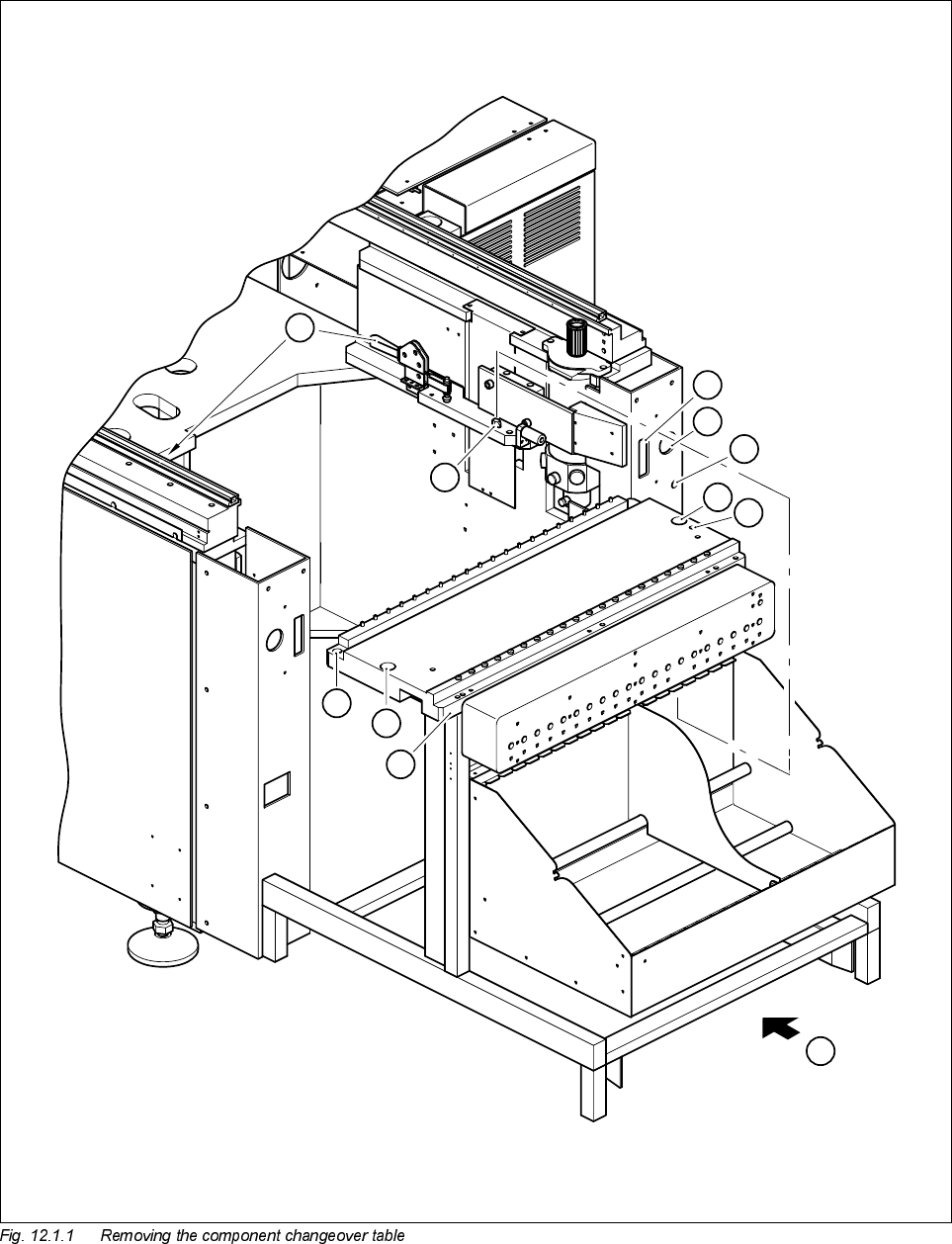
Key to Fig. 12.1.1
5HSODFLQJWKH,&YLVLRQFDPHUDDQGLOOXPLQDWLRQ
FRQWUROERDUG6,3/$&()
NOTE
Make sure that you always replace the IC vision camera and the illumination control board Y1019 as a pair
since the two components are adjusted to each other. If you fail to do so, you will have problems with compo-
nent centering.
7RROVLQVSHFWLRQPHDVXULQJDQGWHVWHTXLSPHQWUHTXLUHG
6SDUHSDUWV
5HPRYLQJWKH,&YLVLRQFDPHUD
● Remove the component changeover table as described in Section 12.1, page 12 - 5.
1 Connection for communications interface
2 Connection for the power supply to the component changeover table
3 Compressed air connection
4 Holes for the centering pins
5 Hexagon socket screws fastening the components table
6 Area for setting down the component changeover table
7 Horizontal tension jack
8 Centering pins
A Sliding in the lift truck for the changeover table
Set of hexagon socket screwdrivers
SITEST program
'HVLJQDWLRQ )URPLWHPQXPEHU
SIPLACE 80F component vision camera 00306223-04
Current regulator for IC illumination
(board Y1019 included in the camera package)
00323147-02