80S-20贴片机.pdf - 第328页
9 12-Segment Revolver Head (10000) SIPLACE 80S-20/F4 Service Manual 9.6 Star Complete Edition 07/97 9 - 32
SIPLACE 80S-20/F4 Service Manual 9 12-Segment Revolver Head (10000)
Edition 07/97 9.6 Star Complete
9 - 31
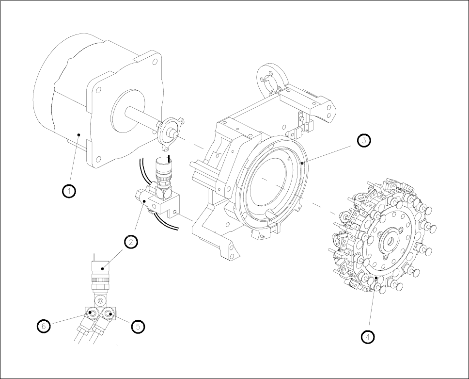
Fig. 9.6.1 Star complete with drive and forced air unit
1 Star motor
2 Forced air unit
3 Front part of the housing
4 Star complete
5 Flow control for pick-up/placement circuit
6 Flow control for reject circuit
9 12-Segment Revolver Head (10000) SIPLACE 80S-20/F4 Service Manual
9.6 Star Complete Edition 07/97
9 - 32

SIPLACE 80S-20/F4 Service Manual 9 12-Segment Revolver Head (10000)
Edition 07/97 9.7 Replacing the Valve for Vacuum / Forced Air and Hose
9 - 33
9.7 Replacing the Valve for Vacuum / Forced Air and
Hose
PLEASE NOTE
This work may only be carried out by Siemens service technicians or by the customer’s appropriately trained
personnel.
Spare parts
SP6-12 valve, from item no. 00319774S02
Plastic hose, silicone, 1.5 x 3.5, natural, from item no. 00323387S01
● Remove the front part of the placement head (see section 9.1.7).
● Remove the star complete (see section 9.6.1).
● Carefully remove the vacuum hose from the segment guide.
● Undo the two slotted head screws (M1.5 x 4) and remove the valve block (see Fig. 9.7.1).
● Watch out for the o-ring located in the base of the star.
● When re-installing the valve and vacuum hose proceed in the reverse sequence of operations.
● To fit the star complete, see section 9.6.2. To record the star axis zero point correction, see section 9.6.3.
ATTENTION ∆
!
∆
!
When fitting the valve block look out for the cutaway in the valve block and the o-ring in the star base. The cut-
away serves as a guide for the valve block.
NOTE
The vacuum hose must be cut precisely to length. Make sure it fits onto the segment guide without twisting.
ATTENTION ∆
!
∆
!
The vacuum hose must not rub against the adjacent vacuum hoses.