80S-20贴片机.pdf - 第451页
SIPLACE 80S-20/F4 Service Manual 13 6-Segment Revolver Head (8000) Edition 07/97 13.9 6x Nozzle Changer 13 - 37 .H\ WR )LJ 1 Spr ing ho ok 2 Ma gazine fo r typ e 7.xx no zzl es 3 Ma gazine fo r typ e 8.xx no z…
13 6-Segment Revolver Head (8000) SIPLACE 80S-20/F4 Service Manual
13.9 6x Nozzle Changer Edition 07/97
13 - 36
5HPRYLQJWKH&RPSOHWH1R]]OH&KDQJHU
7RROUHTXLUHG
– Hexagon socket-head spanner, size 3
6WHSV
● Loosen the 4 M4x50 screws (see Fig. 13.9.1, point 1).
● Carefully raise the complete nozzle changer. Ensure that the compressed air line and the control cable do
not tear as you do this.
● Manually loosen the screws of the connector (9-pin plug) between the control cable and the control board
(see Fig. 13.9.3, item 5).
● Remove the control cable from the control board.
● Open the lock of the quick-release coupling on the valve block (see Fig. 13.9.3, item 7) and pull out the
compressed air hose.
● Lift the complete nozzle changer from the machine.
,QVWDOOLQJWKH&RPSOHWH1R]]OH&KDQJHU
7RROUHTXLUHG
– Hexagon socket-head spanner, size 3
6WHSV
● Lift up the complete nozzle changer in the machine until you can easily connect the compressed air hose
and the control cable.
● Push the compressed air hose into the quick-release coupling as far as the stop.
● Lock the quick-release coupling.
● Connect the control cable and the control board using the connector (9-pin plug).
● Manually tighten the screws on the connector.
● Place the locating holes of the two nozzle changers on the locating pins of the nozzle changer holder.
● Place the 4 M4x50 screws in the corresponding holes (see Fig. 13.9.1, item 1) .
● Tighten the 4 screws using a hexagon socket-head spanner, size 3.
5HSODFLQJWKH0DJD]LQH
6SDUHSDUWV
– Magazine for type 7.xx nozzles, from item no. 00328843-01
– Magazine for type 8.xx nozzles, from item no. 00328842-01
7RROV
– Hexagon socket-head spanner, size 2.5
SIPLACE 80S-20/F4 Service Manual 13 6-Segment Revolver Head (8000)
Edition 07/97 13.9 6x Nozzle Changer
13 - 37
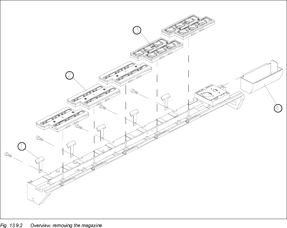
.H\WR)LJ
1 Spring hook
2 Magazine for type 7.xx nozzles
3 Magazine for type 8.xx nozzles
4 Reject container
6WHSVIRU5HPRYLQJWKH0DJD]LQH
You can change the magazines with the nozzle changer being installed.
● Push back the spring hook of the magazine.
● Remove the magazine from the supporting rail. You may feel a slight resistance when you remove the
magazine. This is normal since the magazine is also secured with magnets.
6WHSVIRU,QVWDOOLQJWKH0DJD]LQH
● Place the magazine on the associated locating pins and the advancing pin.
● Press down lightly on the magazine until it is lying on the support and the spring hook snaps in place.

13 6-Segment Revolver Head (8000) SIPLACE 80S-20/F4 Service Manual
13.9 6x Nozzle Changer Edition 07/97
13 - 38
5HSODFLQJWKH6SULQJ+RRNV
6SDUHSDUWV
– Spring hook, from item no. 00329170-01
7RROV
– Hexagon socket-head spanner, size 2.5
6WHSVIRUUHSODFLQJWKHVSULQJKRRN
● Remove the nozzle changer from the machine as described in section 13.9.1.
● Loosen the fixing screw on the spring hook and remove the spring hook
(see Fig. 13.9.2, item 1).
● Insert the new spring hook into the corresponding recess.
● Insert and tighten the fixing screw on the spring plate.
● Install the nozzle changer in the machine as described in section 13.9.2.
5HSODFLQJWKH1R]]OH&KDQJHU&RQWURO%RDUG
6SDUHSDUWV
– Nozzle changer control board, item no. 00317353-02
7RROV
– Hexagon socket-head spanner, size 2.5
6WHSVIRU5HPRYLQJWKH1R]]OH&KDQJHU&RQWURO%RDUG
● Remove the nozzle changer from the machine as described in section 13.9.1.
● Remove the connecting cable between the 5/2-way valve and plug X2 on the control board.
● Loosen the 4 M3x8 screws (see Fig. 13.9.3, item 6).
● Remove the control board by moving it towards the reject station (see Fig. 13.9.3,
item 4). When you do this, be careful not to damage the actuating plate of the light barrier.
PLEASE NOTE
Do not carry out any work on the actuating plate of the light barrier. This plate is set and coated at the factory.