80S-20贴片机.pdf - 第449页
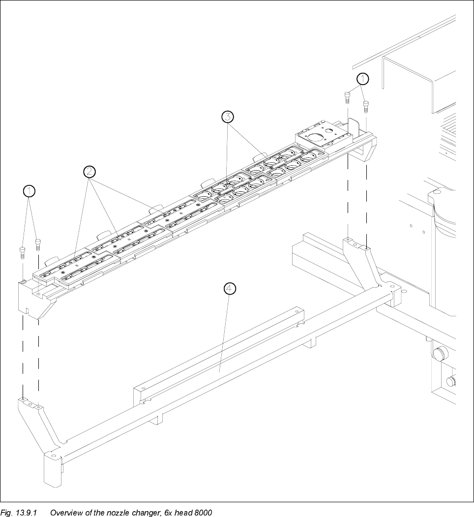
SIPLACE 80S-20/F4 Service Manual 13 6-Segment Revolver Head (8000) Edition 07/97 13.9 6x Nozzle Changer 13 - 35 13.9 6x Nozzl e Ch ange r .H\ WR )LJ 1 Fix ing sc rews for the no zzle changer 2 Ma gazine fo r 7…
13 6-Segment Revolver Head (8000) SIPLACE 80S-20/F4 Service Manual
13.8 Replacing the Star Brake Edition 07/97
13 - 34
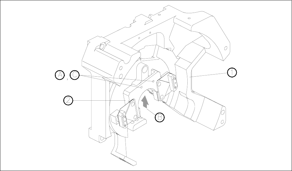
Fig. 13.8.1 Star brake
1 Front part of placement head
2 Star brake
A Undo the M1.6x5 hexagon socket screw
B Using your forefinger, lightly press the brake against the screw.
C Tighten up the hexagon socket screw.
13.8.4 Adjustment Work
● Check the travel times of the star in accordance with the adjustment instructions using the SITEST pro-
gram.
● Calibrate the components camera as described in the SITEST instructions.
13 6-Segment Revolver Head (8000) SIPLACE 80S-20/F4 Service Manual
13.9 6x Nozzle Changer Edition 07/97
13 - 36
5HPRYLQJWKH&RPSOHWH1R]]OH&KDQJHU
7RROUHTXLUHG
– Hexagon socket-head spanner, size 3
6WHSV
● Loosen the 4 M4x50 screws (see Fig. 13.9.1, point 1).
● Carefully raise the complete nozzle changer. Ensure that the compressed air line and the control cable do
not tear as you do this.
● Manually loosen the screws of the connector (9-pin plug) between the control cable and the control board
(see Fig. 13.9.3, item 5).
● Remove the control cable from the control board.
● Open the lock of the quick-release coupling on the valve block (see Fig. 13.9.3, item 7) and pull out the
compressed air hose.
● Lift the complete nozzle changer from the machine.
,QVWDOOLQJWKH&RPSOHWH1R]]OH&KDQJHU
7RROUHTXLUHG
– Hexagon socket-head spanner, size 3
6WHSV
● Lift up the complete nozzle changer in the machine until you can easily connect the compressed air hose
and the control cable.
● Push the compressed air hose into the quick-release coupling as far as the stop.
● Lock the quick-release coupling.
● Connect the control cable and the control board using the connector (9-pin plug).
● Manually tighten the screws on the connector.
● Place the locating holes of the two nozzle changers on the locating pins of the nozzle changer holder.
● Place the 4 M4x50 screws in the corresponding holes (see Fig. 13.9.1, item 1) .
● Tighten the 4 screws using a hexagon socket-head spanner, size 3.
5HSODFLQJWKH0DJD]LQH
6SDUHSDUWV
– Magazine for type 7.xx nozzles, from item no. 00328843-01
– Magazine for type 8.xx nozzles, from item no. 00328842-01
7RROV
– Hexagon socket-head spanner, size 2.5