80S-20贴片机.pdf - 第209页
SIPLACE 80 S-20/F4 Service Manual 7 Components Table Edition 03/97 7.1 Overview 7 - 7 7.1.3 Empty T ape Cutting Device 7.1.3. 1 Elect rical / Pneuma tic S ystems – The vol tage su pply (30 V DC ) and th e contro l of the…
7 Components Table SIPLACE 80 S-20/F4 Service Manual
7.1 Overview Edition 03/97
7 - 6
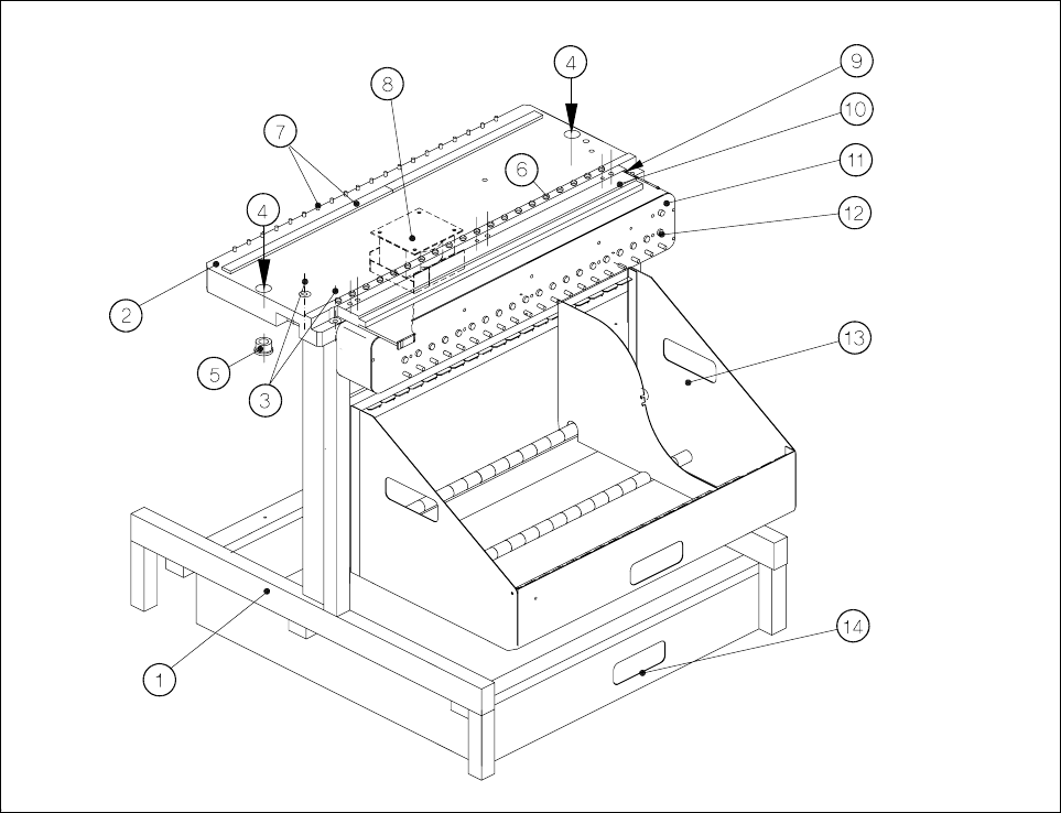
7.1.2 Components Changeover Tables: Structure / Subassemblies
Fig. 7.1.2 Structure of the components changeover tables
Key to Fig. 7.1.2
1Frame
2 Changeover components table, complete, 20-up
3 Mounting of the changeover components table to the frame (4 socket-head cap screws M8)
4 Locating holes in the changeover components table
5 Centering aids in the machine base
6 Spherical caps for centered positioning of the feeder modules
7 Magnetic block and parallel pins for centered positioning of the feeder modules
8 Transformer of components table (power supply for components table)
9 Compressed air connection for the components table compressed air supply
10 Components table compressed air supply for NITTO feeder (option)
11 Communications unit
12 Connections panel for feeder modules
13 Tape container (holds the tape reels)
14 Waste tape container
SIPLACE 80 S-20/F4 Service Manual 7 Components Table
Edition 03/97 7.1 Overview
7 - 7
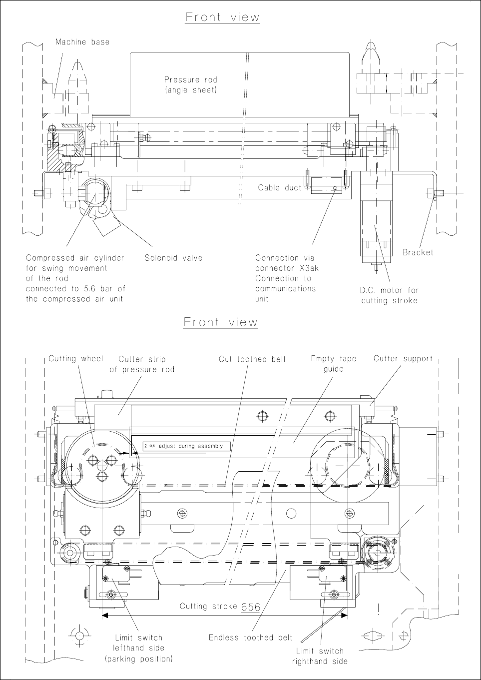
7.1.3 Empty Tape Cutting Device
7.1.3.1 Electrical / Pneumatic Systems
– The voltage supply (30 VDC ) and the control of the empty tape cutting unit is handled by the correspond-
ing communications unit: plug X3ak on the tape cutting unit → "Tape cutter interface" cable Y543-W1 →
plug X37 in the machine base → "Components table interface" cable Y559-W1 → communications unit.
– In the event of overload the direct current geared motor (30 VDC) will be switched out by the PTC ther-
mistor (communications unit). Once the cause has been corrected (stiffness) and the resistor cooled down
the cutting cycle can be restarted.
– The (double-acting) compressed air cylinder is connected directly to the 5.6 bar compressed air branch (=
fixed and preset operating pressure) at the compressed air unit (see Fig. 7.6.6).
– Upon application of compressed air (actuation of the 3/2-way solenoid valve) the plunger retracts,
– after a further actuation of the solenoid valve (= zero-pressure state) the plunger is reset by the two
tension springs on the left and right of the tape cutting unit. This causes the pressure rod to swing in
(see Fig. 7.6.7).
– Damping at the end positions is handled by the tube restrictor inserts in the supply and exhaust air
connections.
– Motor (cutting stroke) and solenoid valve (swing movement) are operated in parallel.
– When the machine is switched off the pressure rod is kept in the swung-in position by the two tension
springs on the left and right of the tape cutting unit (see Fig. 7.1.3).
7.1.3.2 Functional Sequence
● After the machine has been switched on (compressed air is on, d.c. motor is not activated) the pressure
rod swings away from the empty tape channel (see Fig. 7.1.3) → during the cycling of the feeder module
which follows, the empty tape can slip downwards in the empty tape channel .
● After (at the present time) every fourth belt cycle the motor of the empty tape cutting unit is activated and at
the same time the solenoid valve at the compressed air cylinder actuated.
● The compressed air cylinder goes to zero pressure → the two tension springs swing in the pressure rod
(see Fig. 7.6.9) → the carriage with cutter wheel travels to the right (= cutting stroke) → the empty tape is
cut away.
● When the end of cutting stroke (656 mm) is reached the carriage triggers the right-hand limit switch → the
direction of rotation of the motor is changed → the carriage returns to its starting position and triggers the
left-hand limit switch (= parking position ) → the motor current is switched off → the solenoid valve
switches and the compressed air cylinder retracts → the pressure rod (angle section) swings away and
releases the empty tape which drops into the waste tape container.
● The sequence repeats itself as described above (from the second paragraph).
7 Components Table SIPLACE 80 S-20/F4 Service Manual
7.1 Overview Edition 03/97
7 - 8
Fig. 7.1.3 Empty tape cutting unit : mounting in the machine base, structure and connections