80S-20贴片机.pdf - 第380页
12 Vision s ystems SIPLA CE 80S-20/F4/F5 Service Manual 12.6 Coplanarity Option Edition 09/99 12 - 28
SIPLACE 80S-20/F4/F5 Service Manual 12 Vision systems
Edition 09/99 12.6 Coplanarity Option
12 - 27
12 Vision systems SIPLACE 80S-20/F4/F5 Service Manual
12.6 Coplanarity Option Edition 09/99
12 - 28

SIPLACE 80S-20/F4/F5 Service Manual 12 Vision systems
Edition 09/99 12.6 Coplanarity Option
12 - 29
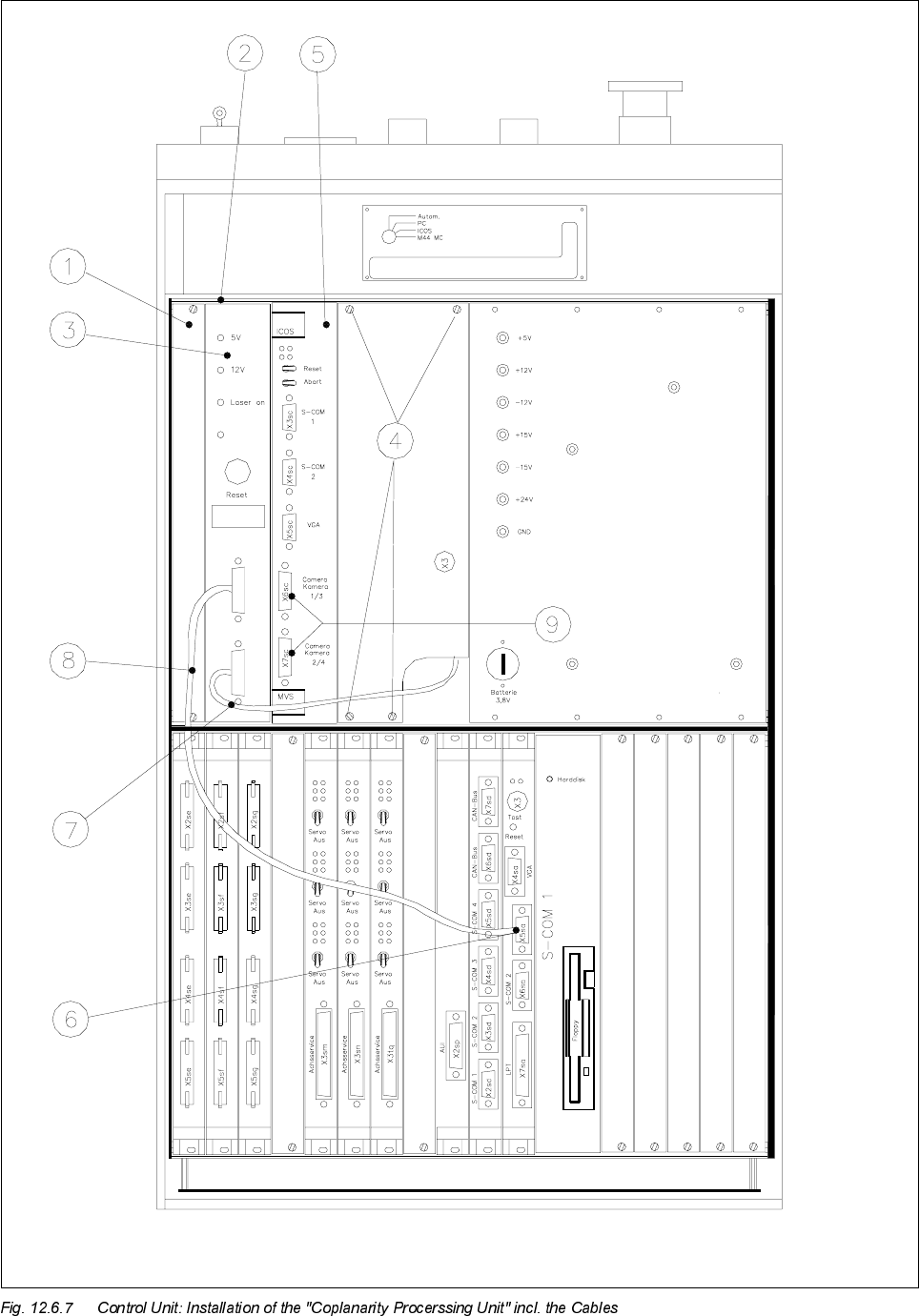
Key to Fig. 12.6.7 (look to your left):
1) Front subpanel, 2) 2 guide rails and 2 contact springs
Fasteners: 2 collar screws, slotted M2.5 x 11 per rail
3) Control unit : Coplanarity processing unit and 4) Fasteners for cover plate
15-pin connector X98 on back of control unit (4 Torx screws)
5) ICOS (on older control units the ICOS may also 6) Machine controller, COM 1
be located in the bottom row of plug-in slots ) (V 24 interface)
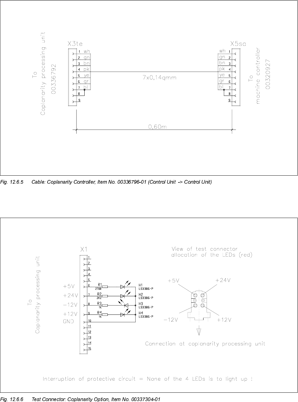
7) "Sensor cable coplanarity" 8) Cable: Coplanarity machine controller
9) These 2 connectors project over on the left
and must therefore be dismantled before
disassembly of coplanarity processing unit.
NOTE in re *)
for the Siemens service engineer:
For details about the cable "Coplanarity" (= cable harness X98 -> Power pack) -> Refer to: "Retrofitting
Instructions for Coplanarity Option", Item No. 00190 585-04.