80S-20贴片机.pdf - 第348页
11 Control Unit SIPLACE 80S-20/F4 Service Manual 11.1 Replacing Modules E dition 03/97 11 - 6 1 1.1.5 Replacing the H ard Disk / Floppy Disk Board Spare par ts Floppy/wi ncheste r AMS-M34 9-A100, f rom it em no. 003 1970…
SIPLACE 80S-20/F4 Service Manual 11 Control Unit
Edition 03/97 11.1 Replacing Modules
11 - 5
11.1.4 Replacing Computer M44 (Machine
Controller)
Spare parts
Computer MC AMS M44-A66, from item no. 00318558-01
● Disconnect all plug-in connections on the front cover of the
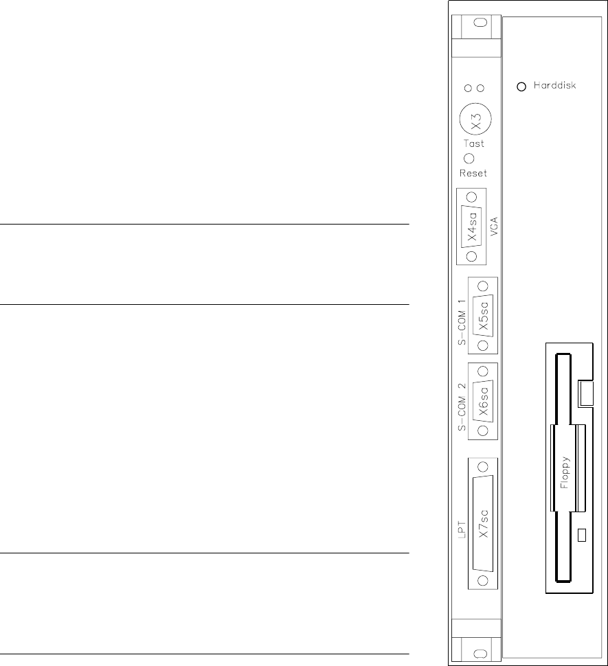
machine controller (plug x3, x4 sa, x5 sa; see Fig. 11.1.2).
● Undo the MC board’s front cover mounting screws (2 slotted-
head screws) and the hard disk / floppy disk board mounting
screws (4 slotted head screws).
NOTE
The MC and hard disk / floppy disk boards are connected by two
short ribbon cables.
● Carefully pull out the MC and the hard disk / floppy disk boards
simultaneously.
● Carefully pull out the boards and place them on an ESD-
checked surface.
● Check the wrap wiring of the new machine controller against the
list (see Section 11.3).
● Disconnect the connecting cable between the machine control-
ler and the hard disk / floppy disk board.
● Connect the new MC board to the hard disk / floppy disk board.
● To fit the boards proceed in the reverse sequence of operations.
NOTE
When inserting the connecting plugs make sure you have the cor-
rect slots on the front panel.
Should you have lost the setup data for the M44 see Section 11.2.
Fig. 11.1.2 Computer M44
hard disk drive/
floppy drive

11 Control Unit SIPLACE 80S-20/F4 Service Manual
11.1 Replacing Modules Edition 03/97
11 - 6
11.1.5 Replacing the Hard Disk / Floppy Disk Board
Spare parts
Floppy/winchester AMS-M349-A100, from item no. 00319704-01
● Disconnect all plug-in connections on the front panel of the machine controller (plugs x3, x4 sa, x5 sa; see
Fig. 11.1.2).
● Unscrew and remove the MC board front panel mounting screws (2 slotted-head screws) and the hard disk /
floppy disk board mounting screws (4 slotted-head screws).
NOTE
The MC and hard disk / floppy disk boards are connected together by two short cables.
● Carefully pull out the MC and hard disk / floppy disk boards. Place the boards on an ESD-checked surface.
● Disconnect the connecting cables between the boards (see the section Replacing Computer M44).
● Insert the new hard disk / floppy disk board into the MC board.
● To fit the boards proceed in the reverse sequence of operations.
NOTE
When inserting the connecting plugs make sure you have the correct slots on the front panel. Should you have
lost the setup data for the M44 see Section 11.2.
● Switch the machine on and install the current station software (see Adjustment instructions) .
● Copy the original MA data from the backup copy onto the hard disk.
SIPLACE 80S-20/F4 Service Manual 11 Control Unit
Edition 03/97 11.2 Set-Up Configuration of M44 Computer (Machine Controller)
11 - 7
11.2 Set-Up Configuration of M44 Computer (Machine
Controller)
● Switch off the machine.
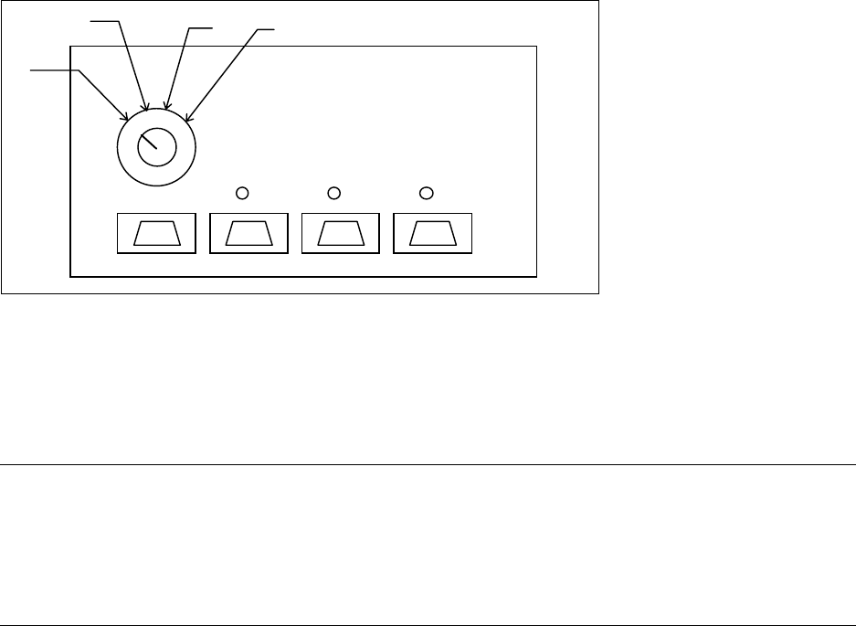
● Switch the monitor to the M44 computer on the multiplexer. (Switch setting: 4 for M44, see Fig. 11.2.1).
Fig. 11.2.1 Multiplexer above control unit
● Unplug the keyboard from the station computer and plug it into the machine controller (the socket is next to
the station computer).
● Switch on the machine and press the keys
Ctrl - Alt - Ins (Strg - Alt - Einfg) when you are requested to do
so.
NOTE
To change the data you will need to use the numerical keypad. This is included in a normal keyboard. The
keys are marked with violet numbers and characters in their top left corner (for example, keys 7-0, U-P, J-
ö, and so on).
Press the Fn key to activate the numerical keypad function of the individual keys.
● Switch the monitor to automatic mode on the multiplexer (switch setting: 1 see Fig. 11.2.1).
11.2.1 Configuration Data
11.2.1.1 Screen 1
Date: tt. mmm jjjj
Time: hh:mm:ss
Drive A: 1.44, 3 ½ in.
Drive B: None
Video: EGA / VGA
1
2
3
4