80S-20贴片机.pdf - 第371页
SIPLACE 80S -20/F4/F5 S ervice Man ual 12 Vision systems Edition 09/99 12.5 Replacing the undergantry PCB cam era 12 - 19 Key to Fig. 12.5.1 ,QVW DOOLQJW KHERDUG XQGHUJDQWU\FDPHUD ● When fi tting, pr oceed in …
12 Vision systems SIPLACE 80S-20/F4/F5 Service Manual
12.5 Replacing the undergantry PCB camera Edition 09/99
12 - 18
5HSODFLQJWKHXQGHUJDQWU\3&%FDPHUD
7RROVLQVSHFWLRQPHDVXULQJDQGWHVWHTXLSPHQWUHTXLUHG
6SDUHSDUWV
5HPRYLQJWKH3&%XQGHUJDQWU\FDPHUD
● Move the gantry whose undergantry camera is to be replaced until the gantry is positioned over the board
conveyor belt.
DANGER
Switch the machine off and disconnect it from the main power supply.
● Starting at the center, remove about 6 feeder modules from the components table above which the under-
gantry camera is to be replaced. Note down the order of the feeder modules you removed or have the set-
up printed out by the line computer. This will help prevent set-up errors later on.
● Place the mirror on the unoccupied location.
● Slide the gantry above the mirror by hand.
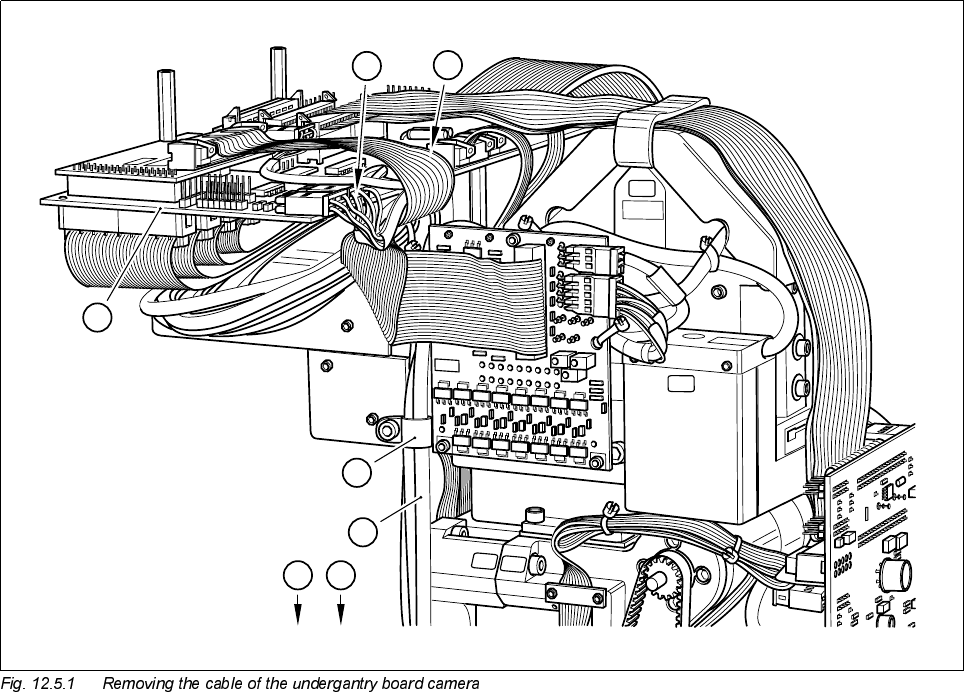
● Undo the four cable clips for the board camera cable from the revolver head and gantry
(see A in Fig. 12.5.1).
● Disconnect the plug of the board camera cable from plug X8 of conversion board C0005 (see B in Fig.
12.5.1).
● Pull the board camera cable out of the cable clips.
● With the aid of the mirror ascertain the position of the mounting screws.
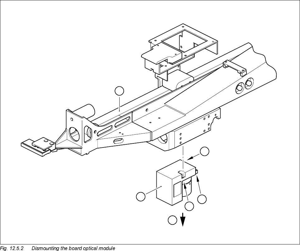
● Undo the three M2 x 10 hexagon socket screws (see A in Fig. 12.5.2 page 12 - 20) which fasten the board
undergantry camera (see ➁ in Fig. 12.5.2 page 12 - 20) to the gantry (see
➀
in Fig. 12.5.2). While doing so
hold the board camera with your free hand.
Set of hexagon socket screwdrivers
Mirror
SITEST program
'HVLJQDWLRQ )URPLWHPQXPEHU
PCB optical module 00315224-01
SIPLACE 80S-20/F4/F5 Service Manual 12 Vision systems
Edition 09/99 12.5 Replacing the undergantry PCB camera
12 - 19
Key to Fig. 12.5.1
,QVWDOOLQJWKHERDUGXQGHUJDQWU\FDPHUD
● When fitting, proceed in the reverse sequence of actions Section 12.5.3, page 12 - 18.
● Check once more the correct seating of the plug and cable.
6HWWLQJZRUN
● Calibrate the board undergantry camera with the aid of the SITEST program.
● Replace the feeder modules which you removed. Make sure they are fitted to the components table in the
correct order.
1 Conversion board ’small axis C0005’
2 Undergantry PCB camera cable
A Cable clips
B Connecting the board camera cable to the conversion board C0005
0240
0025
0025
0240
0240
1
A
B
A
2
AA