80S-20贴片机.pdf - 第398页
12 Vision s ystems SIPLA CE 80S-20/F4/F5 Service Manual 12.6 Coplanarity Option Edition 09/99 12 - 46 &KHFN 3RVLWLRQ RI&RSODQD ULW\ 6H QVRU ! 9 [[ 12.6. 17.1 Overview NOTE For the ex ecution of test …
SIPLACE 80S-20/F4/F5 Service Manual 12 Vision systems
Edition 09/99 12.6 Coplanarity Option
12 - 45
● If desired, actuate the “Display” button to see the measured values.
● Terminate the menu “COPLANARITY”.
● Terminate the SITEST program.
● Answer “YES” to the question being displayed: “Store the data?”
The offset values for X, Y and Z are entered in the real.ma data under coplanarity_2_x /.... _y /.... _z .
● Press EMERGENCY OFF and remove the calibration tool.
● As the final step, check whether the IC camera and flip-chip camera function.
,Q&DVHRI3UREOHPVRU(UURUV
12 Vision systems SIPLACE 80S-20/F4/F5 Service Manual
12.6 Coplanarity Option Edition 09/99
12 - 46
&KHFN3RVLWLRQRI&RSODQDULW\6HQVRU!9[[
12.6.17.1Overview
NOTE
For the execution of test commands 3 and 8 see Section 12.6.18, Run Data Protocol (German: ADP).
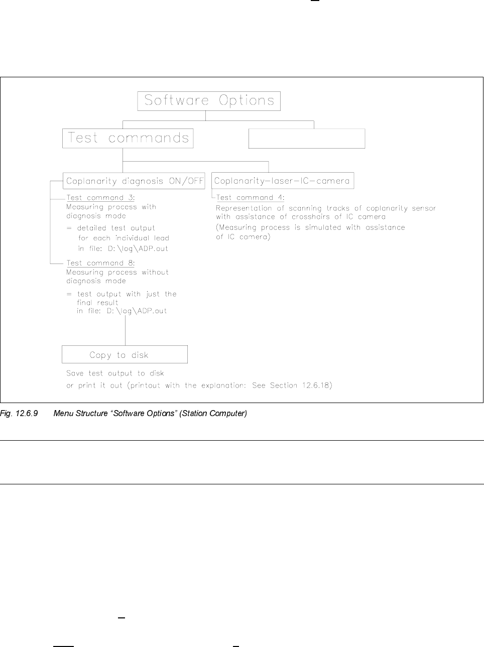
You can utilize test command 4 (see Fig. 12.6.9) to check whether the laser track strikes the leads.
- The component to be measured is optically centered after test command 4 is called up. Instead of being
moved over the coplanarity sensor, it is moved over the camera., i.e., the measurement process is there-
fore simulated.
- The midpoint of the IC camera (crosshairs) corresponds to the focus point of the coplanarity sensor.
12.6.17.2Procedure (> V 403.xx)
● Execute only in case of software version 403.04 -> D:\DAT\SST.MA, speed factor:
If this value is > 200 reduce the value to 200 (= higher accuracy).

SIPLACE 80S-20/F4/F5 Service Manual 12 Vision systems
Edition 09/99 12.6 Coplanarity Option
12 - 47
CAUTION O
It is not permissible to change the entered speed factor in the case of V 404.xx.
● Restart the machine to transfer the revised data.
● Activate the submenu “Test command 4” in the menu “Software options”
● Turn the cycle mode on.
● Move the PCB into the center conveyor (placement conveyor).
● Pick up the component during the cycle mode.
The component is optically centered after being picked up.
● Use “ALT 8” to switch the camera to the monitor.
● Move the component over the IC camera:
The component is moved to a position at which the first row of leads is over the IC camera.
During this process, the IC camera simulates the coplanarity sensor.
The cross in the center of the screen represents the focal point of the coplanarity sensor.
The start and end positions of the scanning track are shown on the monitor.
NOTE
The order in which lead rows are positioned over the IC camera as shown in Fig. 12.6.10 corresponds to the
order of positioning and/or scanning during the coplanarity measurement.
During the simulation of the measurement, the error message "Measurement error! Coplanarity cannot
execute command" is reported -> you can ignore this message.