80S-20贴片机.pdf - 第446页
13 6-Segment Revolver Head (8000) SIPLACE 80S-20/F4 Service Manual 13.7 Replacing the Valve for Vacu um / Forced Air and Hose E dition 07/97 13 - 32 Fig. 13.7.1 V acuum / forced air valve and hose 1 Star comp lete 2O - r…

SIPLACE 80S-20/F4 Service Manual 13 6-Segment Revolver Head (8000)
Edition 07/97 13.7 Replacing the Valve for Vacuum / Forced Air and Hose
13 - 31
13.7 Replacing the Valve for Vacuum / Forced Air and
Hose
PLEASE NOTE
This work may only be carried out by Siemens service technicians or by the customer’s appropriately trained
personnel.
Spare parts
Valve for SP6, from item no. 00324955S01
Plastic hose, silicone, 1.5 x 3.5, natural, from item no. 00323387S01
● Remove the front part of the placement head (see section 13.1.7).
● Remove the star complete (see section 13.6.1).
● Carefully remove the vacuum hose from the segment guide.
● Undo the two slotted head screws (M1.5 x 4) and remove the valve block (see Fig. 13.7.1).
● Watch out for the o-ring located in the base of the star.
● When re-installing the valve and vacuum hose proceed in the reverse sequence of operations.
● To fit the star complete, see section 13.6.2. To record the star axis zero point correction, see section
13.6.3.
ATTENTION ∆
!
∆
!
When fitting the valve block look out for the cutaway in the valve block and the o-ring in the star base. The cut-
away serves as a guide for the valve block.
NOTE
The vacuum hose must be cut precisely to length. Make sure it fits onto the segment guide without twisting.
ATTENTION ∆
!
∆
!
The vacuum hose must not rub against the adjacent vacuum hoses.
13 6-Segment Revolver Head (8000) SIPLACE 80S-20/F4 Service Manual
13.7 Replacing the Valve for Vacuum / Forced Air and Hose Edition 07/97
13 - 32
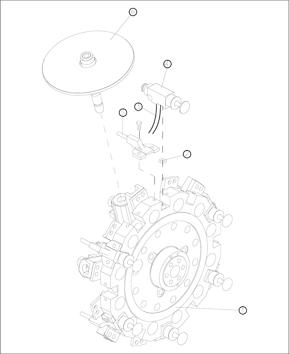
Fig. 13.7.1 Vacuum / forced air valve and hose
1 Star complete
2O-ring
3Hose
4 Valve block
5 Forced air supply
6Sleeve

SIPLACE 80S-20/F4 Service Manual 13 6-Segment Revolver Head (8000)
Edition 07/97 13.8 Replacing the Star Brake
13 - 33
13.8 Replacing the Star Brake
13.8.1 Tools and Test Equipment
Hexagon socket screw keys, set
SITEST program
Adjustment instructions
13.8.2 Spare Parts
Brake for star, complete, from item no. 00328781S01
13.8.3 Replacing the Brake
● Remove the front part of the placement head (see section 13.1.7, page 13 - 7).
● Undo the two M1.6x5 hexagon socket screws (see pos. A of Fig. 13.8.1).
● Replace the brake and fix the brake in place using the hexagon socket screw - do not tighten up the screw
yet.
● Using your forefinger press the brake lightly against the two hexagon socket screws (see pos. B of Fig.
13.8.1). The brake is now correctly positioned.
● Tighten up both hexagon socket screws.
● Reinstall the front part of the placement head (see section 13.1.6, page 13 - 6).
NOTE
When you remove or re-install the front part of the placement head note that the star is rotated by 15° out of its
zero position (vertical sleeve position).
When you fit the front part of the placement head, make sure that the distributor disc (see pos. 3, Fig. 13.4.2,
page 13 - 18) is positioned correctly.