80S-20贴片机.pdf - 第170页
6 PCB Handling SIPLACE 80S-20/F4 Service Manual 6.3 Drive Units of the PCB Transportation Systems E dition 01/96 6 - 14 ● Careful ly slide t he drive unit in th e direc tion of the movab le side of the bo ard conv eyor (…

SIPLACE 80S-20/F4 Service Manual 6 PCB Handling
Edition 01/96 6.3 Drive Units of the PCB Transportation Systems
6 - 13
6.3 Drive Units of the PCB Transportation Systems
6.3.1 Replacing the drive unit of the input conveyor
Spare parts, auxiliary materials and equipment
Drive unit, transfer conveyor, fixed right-hand, Item No. 00324315-01 consisting of:
1 geared motor with synchronizing disk
1 motor mount
2 bearing bushes
1 synchronizing disk Al 8T2.5/25-0
1 synchronizing disk Al 13,5 T5/13-0
2 deep-grooved ball bearings 7 x 19 x 6 607-2Z
1 Synchroflex 6 T2.5/245 toothed belt
SITEST program
NOTE
The drive unit can only be replaced as a complete unit.
6.3.1.1 Removing the input or output conveyor drive units
NOTE OOO
It is essential that you also comply with the safety instructions given in Chapter 1.
● Select the maximum width setting for the board conveyor so that you can carry out servicing work unim-
peded.
● Move the gantry or gantries to outside the board transportation area.
● Switch off the machine at the main switch and disconnect it from the main power supply.
● Make sure that the machine cannot be switched on while you are carrying out servicing work.
● Undo and remove the two M3 hexagon socket screws of the sonar BERO mount (A).
● Carefully place the mount together with the sonar BERO on the machine base.
● Make sure that the connection cable does not get kinked or bent too tightly.
● Remove the cable shoes from the motor terminals.
● Strip from the motor the heat-shrinkable sleeves which fasten the connecting cable.
● Carry out the following work on the movable side of the board conveyor:
– On the inside unscrew and remove the two M 2 x 5 slotted head screws of the disk on the hexagonal
shaft (B).
– On the outside unscrew and remove the three M 3 x 5 hexagon socket screws in the flange (C).
● Undo and remove the two M4 hexagon socket screws which fasten the drive unit to the side part of the
fixed side of the board conveyor (D).
6 PCB Handling SIPLACE 80S-20/F4 Service Manual
6.3 Drive Units of the PCB Transportation Systems Edition 01/96
6 - 14
● Carefully slide the drive unit in the direction of the movable side of the board conveyor (E).
● Remove the flange and synchronizing disk from the hexagonal shaft.
● Lift the drive unit diagonally upwards and out (F).
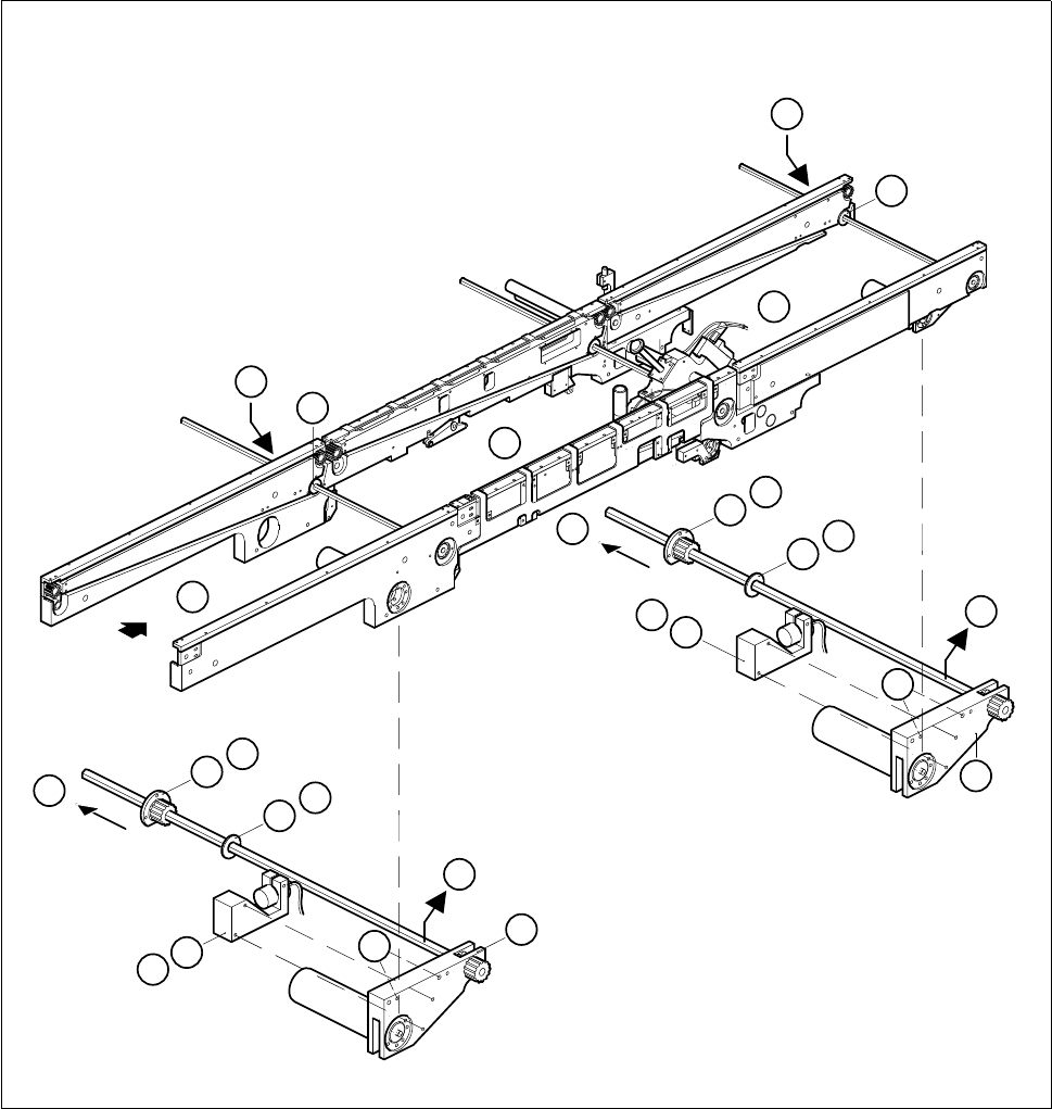
Fig. 6.3.1 Removing the drive unit of the input or output conveyors
Key to Fig. 6.3.1
1 Input conveyor 2 Center conveyor
3 Output conveyor 4 Sonar BERO mount of input / output conveyor
5 Drive unit of input / output conveyor 6 Center conveyor drive unit
7Disk 8Flange
3
1
2
5
7
8
8
7
4
E
8
7
A
B
C
D
F
4
E
8
7
A
B
C
D
5
F

SIPLACE 80S-20/F4 Service Manual 6 PCB Handling
Edition 01/96 6.3 Drive Units of the PCB Transportation Systems
6 - 15
6.3.1.2 Fitting and testing the input and output conveyor drive units
● First of all, slide the synchronizing disk onto the hexagonal shaft. Make sure that the disk is correctly posi-
tioned on account of the countersunk holes.
● Slide the flange with the synchronizing disk onto the hexagonal shaft.
● Mount the drive unit on the fixed side of the conveyor.
● Mount the disk and the flange on the movable side of the conveyor.
● Plug the cable shoes onto the terminals of the geared motor and refer to the circuit diagram folder to make
sure that you have connected the motor up correctly.
● Slide the heat-shrinkable sleeve rings onto the motor to fasten the motor cable.
● Fit the sonar BERO mount.
● Referring to the adjustment instructions, carry out a function test of the conveyor.
NOTE OOO
While carrying out the function test do not fail to observe the safety instructions in Chapter 1.
● Unlock the key-operated switch before performing function testing and making adjustments. This will allow
you to take measurements at the motors with the protective cover open. However the gantry axis systems
will be in a de-energized state.
NOTE O
When you have finished the function test do not forget to lock the key-operated switch again, stowing the
key in a place where unauthorized persons have no access to it.