80S-20贴片机.pdf - 第286页
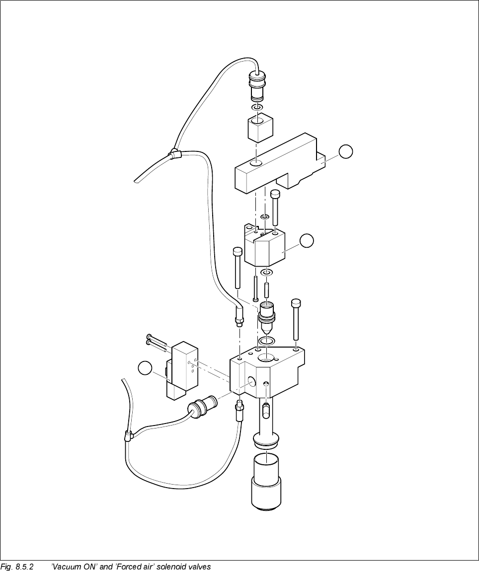
8 IC Head S IPLACE 80S-20/F4 Service Manual 8.5 Servicing W ork on the Pneum atic System Edition 01/97 8 - 24 5HSODFHWKH6LOHQFHU ● Check t he silen cer at regu lar inte rvals for contamin ation, fol lowing the…
8 IC Head SIPLACE 80S-20/F4 Service Manual
8.5 Servicing Work on the Pneumatic System Edition 01/97
8 - 24
5HSODFHWKH6LOHQFHU
● Check the silencer at regular intervals for contamination, following the instructions given in the Mainte-
nance section of the User Manual. To do this, unscrew the silencer and replace if necessary.
&OHDQRU5HSODFHWKH9DFXXP1R]]OH
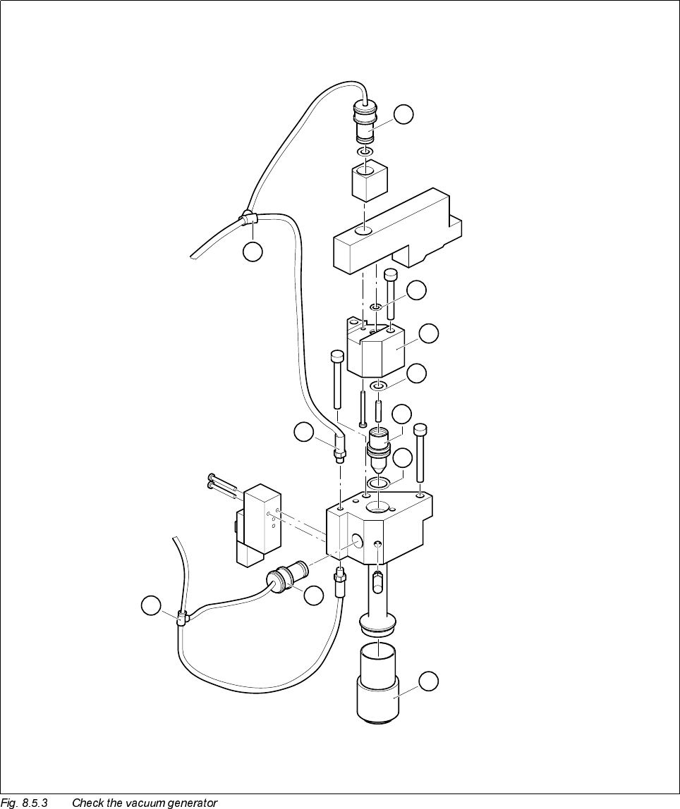
7RGLVDVVHPEOHWKHYDFXXPQR]]OH
● Loosen the two 2.5 mm hexagon socket head screws that fix the spacer in place (item A, Fig. 8.5.3).
● Lift out the spacer and pull the vacuum nozzle out of its hole.
● Check the vacuum nozzle (item 4, Fig. 8.5.3) for dirt and clean if necessary.
● Check the tip of the vacuum nozzle for damage and replace if necessary.
● Check the O-rings in the spacer (item 2) and on the vacuum nozzle (items 3 and 5) for damage. Replace
the O-rings if necessary. Lightly grease the new or cleaned O-rings with UNISILKON L 250L.
7RUHDVVHPEOHWKHYDFXXPQR]]OH
Reverse the above sequence to reassemble.
5HSODFH&ROOHW%XVK3.
● Detach the hose coupling from the connector with the collet bush (item 1 or 7, Fig. 8.5.3).
● Remove the collet bush.
● Ensure that the hole for the collet bush is clean.
● Insert the new collet bush and push it into the hole.
9DFXXP7HVW:LWKWKH6,7(673URJUDP
If the vacuum generator is functioning correctly and the vacuum test with the station software or the SITEST
program still returns incorrect values, the fault may be either on the IC head board or on the CAN bus.
● Use the relevant circuit diagram to trace the fault.
SIPLACE 80S-20/F4 Service Manual 8 IC Head
Edition 01/97 8.5 Servicing Work on the Pneumatic System
8 - 25
Key to Fig. 8.5.3
1 Collet bush PK-3 2 O-ring 3 x 1
3 O-ring 5 x 1.5 4 Vacuum nozzle for IC head
5 O-ring 8 x 1 6 Silencer
7 Collet bush PK-3 8 Hose coupling T-PK-3
9 Nipple with male threaded end 10 Hose coupling T-PK-3
A Remove spacer
8
6
1
7
5
9
10
4
3
2
A