c921199.R00_EN.pdf - 第41页
1-21 1 Handling 8. Daily Inspection and Maintenance Daily inspection and maintenance are necessar y in order to use the tape feeder safely for a long period of time. 8.1 Daily inspection Check the follo wing before using…
1-20
1
Handling
4
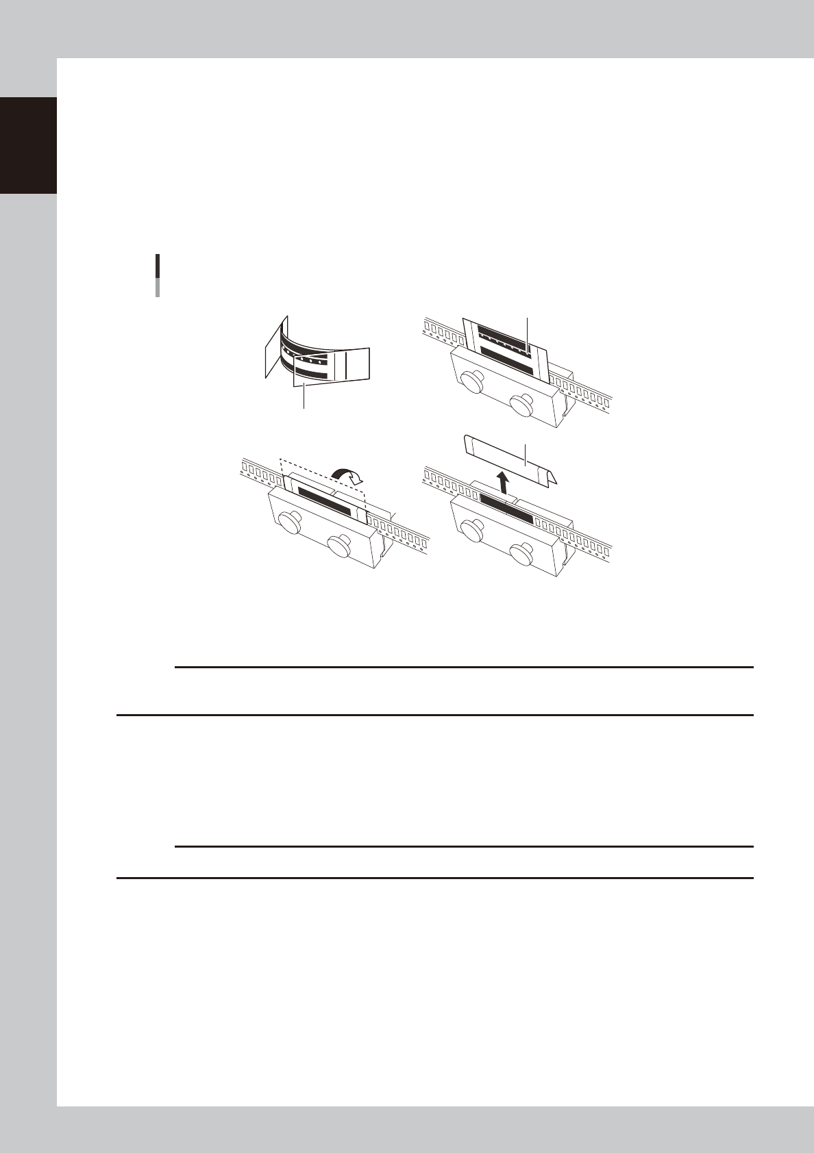
Connect the tape.
Connect the top tape side and the carrier tape side with the connecting tape in the following
procedure.
1. Peel off the ground paper (thick side) from the connecting tape.
2. Stick the connecting tape to the top tape side while pressing the lower edge of the connecting
tape against the upper side of the jig.
3. Fold over the connecting tape along the edge, and make sure it sticks to the carrier tape side as
well. In this state, firmly connect both sides of the carrier tape side and top tape side.
4. Peel off the ground paper (thin side) from the connecting tape.
Connecting the tape
Ground paper (thick side)
Ground paper (thin side)
This tape is to be discarded.
1 2
3 4
64239-9L-00
5
Remove the tape from the tape connecting jig.
Remove the connected tape from the clamping part of the tape connecting jig.
c
CAUTION
If two pieces of the tape are connected without using the jig, pitch difference, misalignment of the tape or removal of
the tape may be caused. Take care or component pickup error may be caused.
n
Splice sensor
An optional splice sensor can be attached to a feeder without a splice sensor.
Please contact Yamaha or its dealer if you want to install a splice sensor.
c
CAUTION
The jigs mentioned above are not necessary for connecting tapes when using a splice sensor.
1-21
1
Handling
8. Daily Inspection and Maintenance
Daily inspection and maintenance are necessary in order to use the tape feeder safely for a long period of
time.
8.1 Daily inspection
Check the following before using the tape feeder.
n
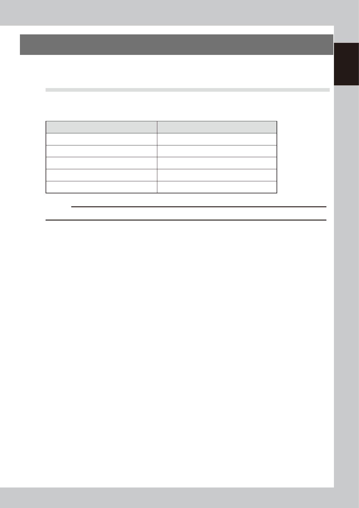
Inspection items
Inspection Items How to solve the problem
Is the clamping lever tight enough? Refer to “6. Clamping lever assembly of Chapter 2”
Is the tape guide assembly tight enough? Refer to “2. Tape guide assembly of Chapter 2”
Are any of the screws loose? Tighten the screws.
Are any of the components deformed or broken? Repair or replace the part.
Are any of the components missing or lost? Repair or replace the part.
c
CAUTION
Check the feeder after removing it from the machine.
1-22
1
Handling
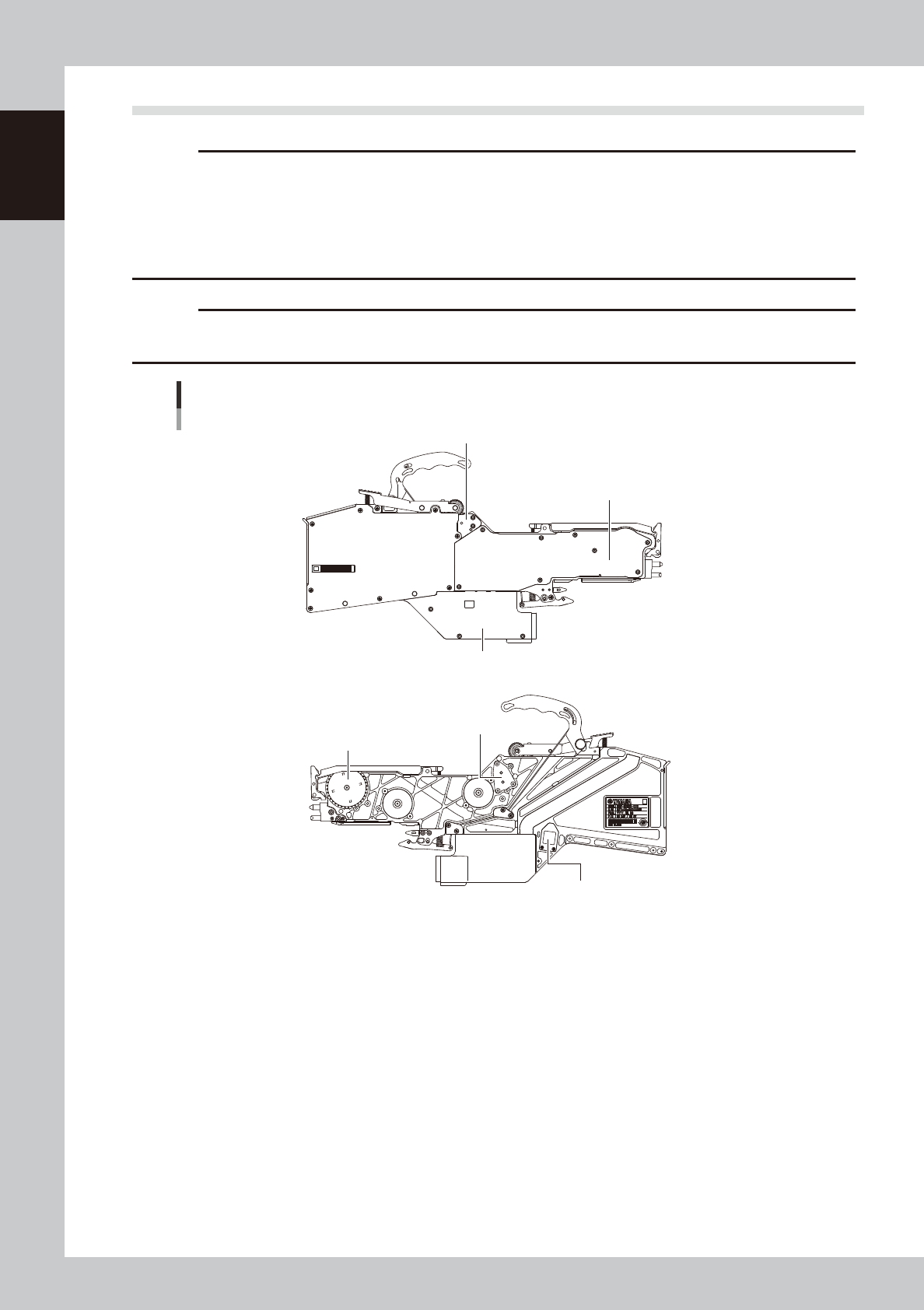
8.2 Precautions for maintenance
c
CAUTION
Never remove the parts shown in the figure below.
· Feeder side cover 1
· EL box cover
· Idle gear cover 1
· Idle gear cover 2
· Splice sensor (if installed)
c
CAUTION
Never touch or grease the part in the figure below.
· Sprocket
Parts in need of attention during maintenance
Idle gear cover 2
Feeder side cover 1
EL box cover
Idle gear cover 1
Sprocket
Splice sensor
63121-9L-10