c921199.R00_EN.pdf - 第67页
2-21 2 Replacing parts 10.2 Installation 1 Install the wire co vers 1 and 2. Install the respective wire covers by tightening the two screws with a Phillips screwdriver (No. 1). • Tightening torque: 30N·cm 63242-9L-00 n …
2-20
2
Replacing parts
10. Wire covers 1 and 2
10.1 Removal
1
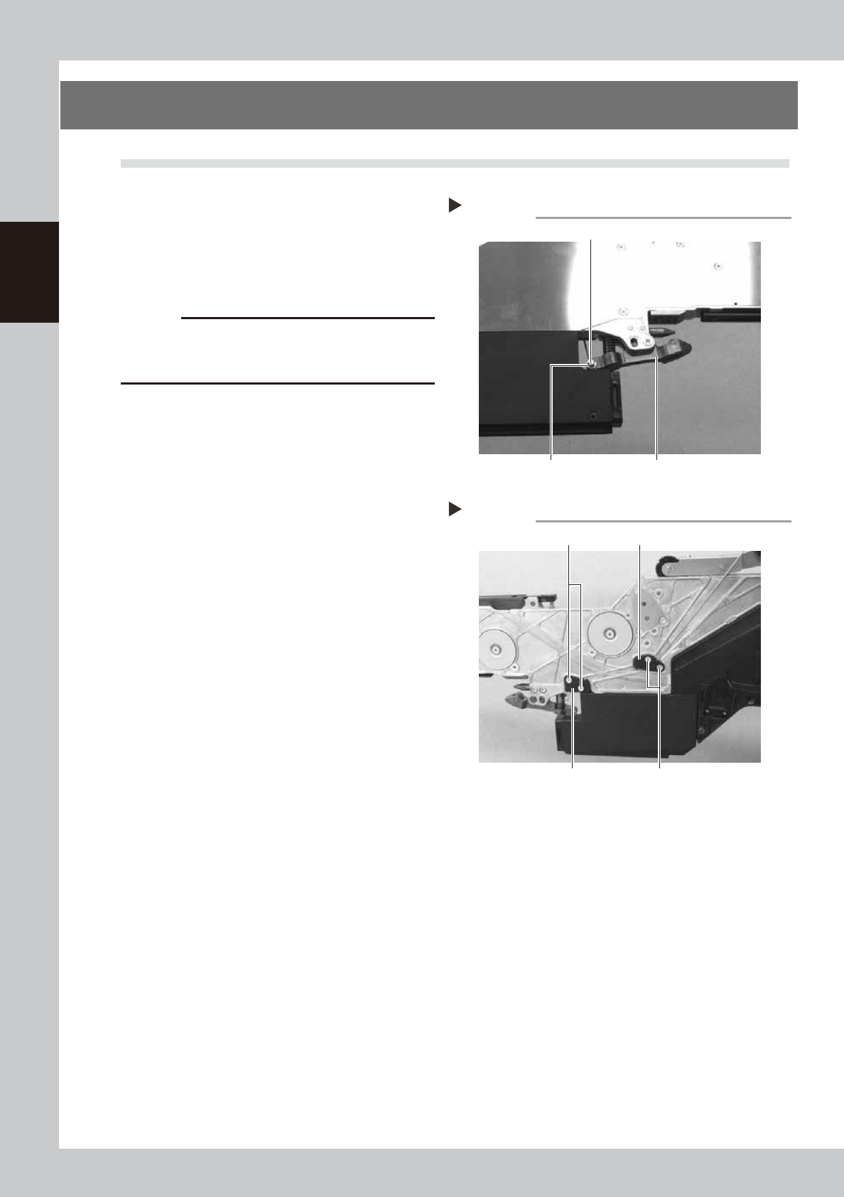
Remove the unclamping wire axis.
Remove the E-ring of the unclamping wire
attached to the clamping lever assembly
with a precision screwdriver (flat-blade) and
remove the axis of the unclamping wire.
63214-9L-00
c
CAUTION
· When removing the E-ring, pay attention not to lose it.
· The E-ring is an exclusive part. If it should be lost, do
not use any E-ring other than the specified one.
2
Remove the wire covers 1 and 2.
Remove the two screws of the respective
wire covers with a Phillips screwdriver (No. 1)
to remove the wire covers.
63232-9L-00
Removing the axis of the unclamping wire
Step 1
Clamping lever assemblyE-ring
Axis of the unclamping wire
Removing the wire covers 1 and 2
Step 2
Wire cover 1 Screw
Wire cover 2Screw
2-21
2
Replacing parts
10.2 Installation
1
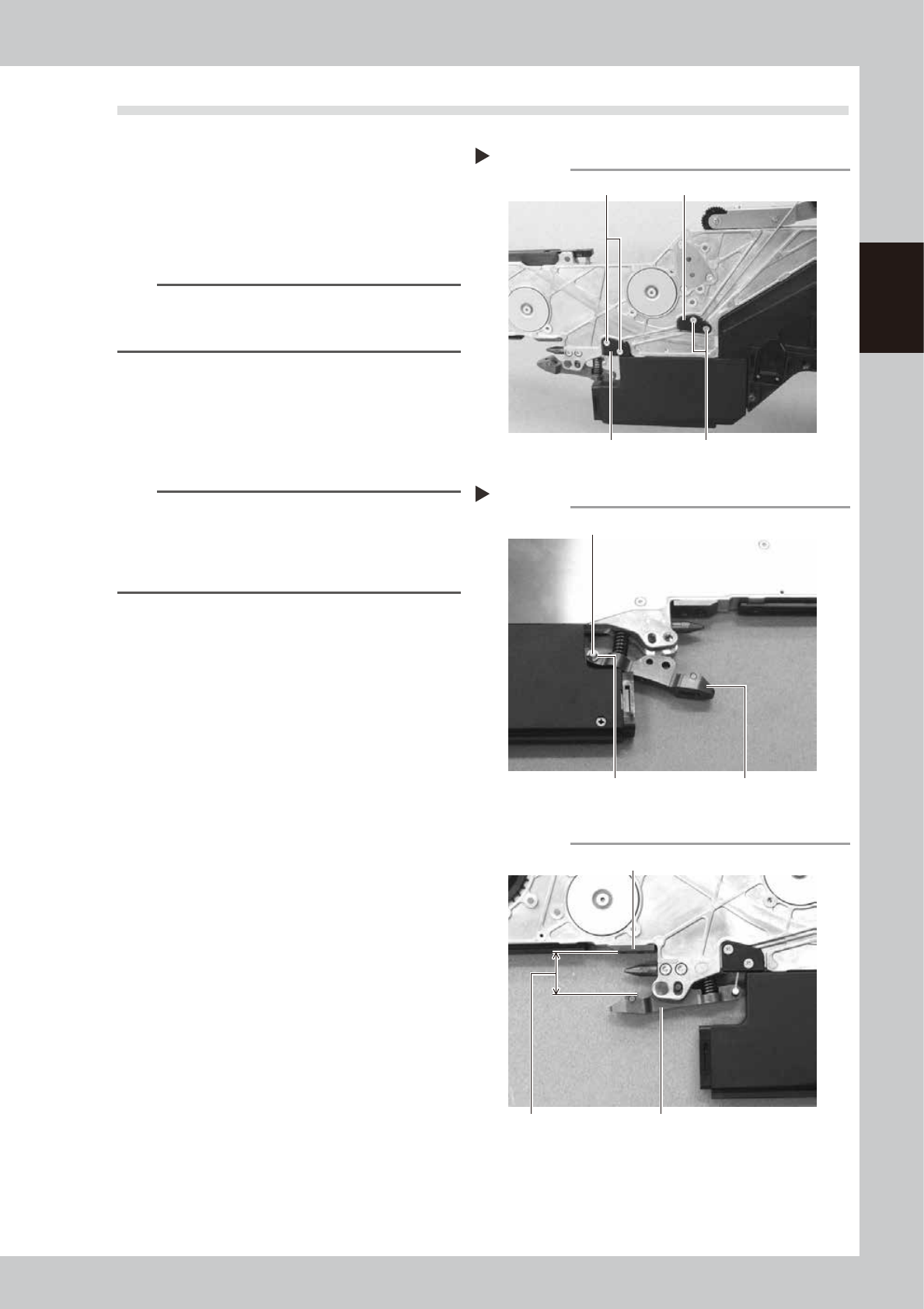
Install the wire covers 1 and 2.
Install the respective wire covers by
tightening the two screws with a Phillips
screwdriver (No. 1).
• Tightening torque: 30N·cm
63242-9L-00
n
NOTE
The wire covers 1 and 2 have grooves for passing a wire
on the back side. Be sure to pass the wire in the
grooves.
2
Install the unclamping wire axis.
Pass the axis of the unclamping wire into the
clamping lever assembly, install the E-ring
and secure the E-ring with longnose pliers.
63243-9L-00
n
NOTE
Check that the distance between the under plate and
the clamping lever assembly is 20 to 21 mm when the
handle is opened. If the distance is out of the range,
adjust the distance by changing the number of the
tension spacer 2.
63239-9L-00
Installing the wire covers 1 and 2
Step 1
Wire cover 1 Screw
Wire cover 2Screw
Installing the axis of the unclamping wire
Step 2
E-ring
Axis of the unclamping wire
Clamping lever assembly
Checking the distance
Under plate
20 – 21mm
Clamping lever assembly
2-22
2
Replacing parts
11. Handle
11.1 Removal
1
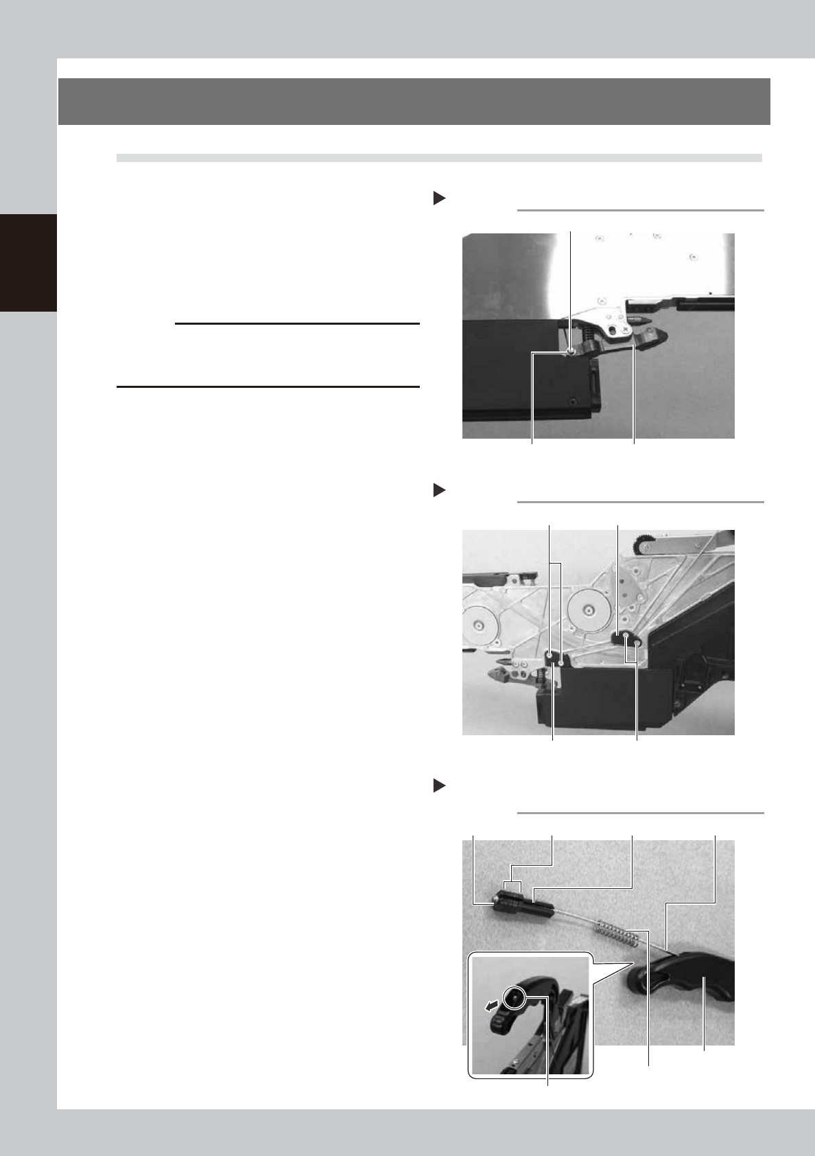
Remove the axis of the unclamping
wire.
Remove the E-ring of the unclamping wire
attached to the clamping lever assembly
with a precision screwdriver (flat-blade) and
remove the axis of the unclamping wire.
63214-9L-00
c
CAUTION
· When removing the E-ring, pay attention not to lose it.
· The E-ring is an exclusive part. If it should be lost, do
not use any E-ring other than the specified one.
2
Remove the wire covers 1 and 2.
Remove the two screws of the respective
wire covers with a Phillips screwdriver (No. 1)
to remove the wire covers.
63232-9L-00
3
Remove the tension spacer 1,
tension spacer 2, wire tension 1
and tension spring.
Pull out the unclamping wire by plucking the
spherical portion at the handle side of the
unclamping wire between the longnose
pliers and remove the tension spacer 1,
tension spacer 2 (some pieces), wire tension
1 and tension spring in the handle.
63233-9L-00
Removing the axis of the unclamping wire
Step 1
Clamping lever assemblyE-ring
Axis of the unclamping wire
Removing the wire covers 1 and 2
Step 2
Wire cover 1 Screw
Wire cover 2Screw
Step 3
Removing the tension spacers 1 and 2,
wire tension 1 and tension spring
Tension spring
Spherical portion of the unclamping wire
Wire tension 1 Tension spacer 1 Unclamping wireTension spacer 2
Handle