c921199.R00_EN.pdf - 第52页
2-6 2 Replacing parts 3 Install the tape guide assembly . Push down the tape guide rear lever and install the tape guide assembly to the body. 63208-9L-10 4 Secure the tape guide assembly . Push down the tape guide assem…
2-5
2
Replacing parts
4
Remove the tape guide front lever.
Loosen the setscrew securing the shaft for
the tape guide front lever with a hexagonal
wrench (1.5) and pull off the shaft.
63206-9L-10
c
CAUTION
There is a spring inside the tape guide front lever. The
tape guide front lever or spring may pop out due to
spring force when the shaft is removed. Take care not
to lose the parts.
3.2 Installation
1
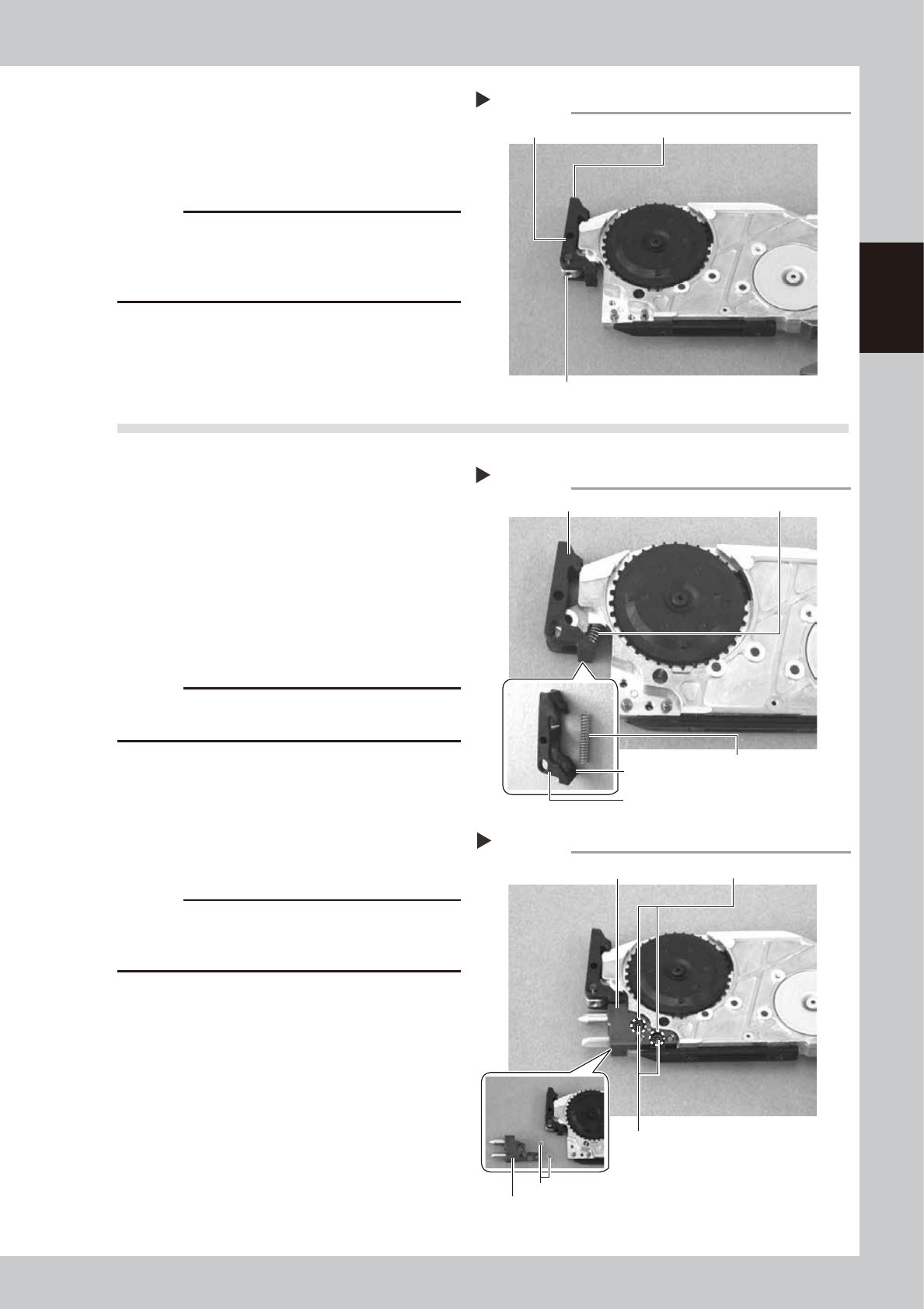
Install the tape guide front lever.
Insert the spring on the protruding portion of
the new tape guide front lever, align the
position of the shaft insertion hole of the
body and the shaft insertion hole of the tape
guide front lever while holding down the
tape guide front lever, insert the shaft and
tighten the setscrew using the hexagonal
wrench (1.5) to secure the shaft.
• Tightening torque: 40N·cm
63207-9L-10
c
CAUTION
Check that the spring load can be felt when aligning
the shaft insertion holes.
2
Install the front block.
Insert the guide hole of the front block to
the guide pin of the body and secure it by
tightening the two bolts using the hexagonal
wrench (2.5)
63011-9L-00
c
CAUTION
If there were two shims installed between the front
block and the body, reinstall the shims securely at the
position where they had been installed.
Step 2
Install the front block
Front block (Shim)
Front block
(Shim)
Bolt
Step 1
Installing the tape guide front lever
Tape guide front lever Spring
Tape guide front lever
Spring
Protruding portion
Step 4
Removing the tape guide front lever
Setscrew
Tape guide front leverShaft
2-6
2
Replacing parts
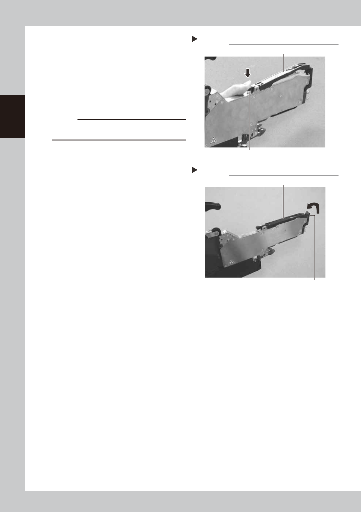
3
Install the tape guide assembly.
Push down the tape guide rear lever and
install the tape guide assembly to the body.
63208-9L-10
4
Secure the tape guide assembly.
Push down the tape guide assembly and
check that it is locked with the tape guide
front lever.
63209-9L-10
c
CAUTION
Check that the sprocket assembly does not interfere
with the tape guide assembly after the installation.
Step 3
Installing the tape guide assembly
Tape guide rear lever
Tape guide assembly
Step 4
Installing the tape guide assembly
Tape guide front lever
Tape guide assembly
2-7
2
Replacing parts
4. Tape guide rear lever
4.1 Removal
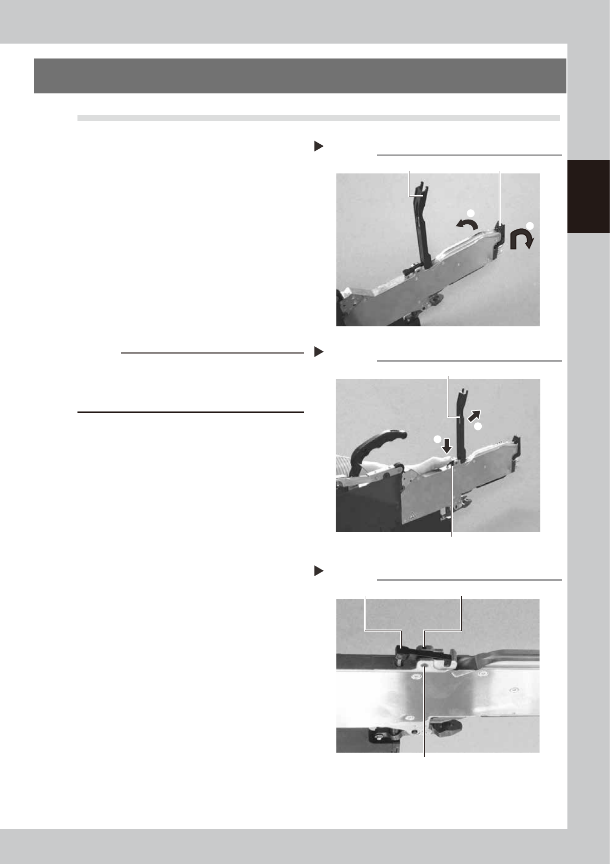
1
Lift the tape guide assembly.
Open the tape guide front lever and lift the
tape guide assembly.
63202-9L-10
2
Remove the tape guide assembly.
Push down the tape guide rear lever and
remove the tape guide assembly from the
body.
63203-9L-10
3
Remove the tape guide rear lever.
Loosen the setscrew securing the shaft for
the tape guide rear lever with a hexagonal
wrench (1.5) and pull off the shaft.
63210-9L-00
c
CAUTION
There is a spring inside the tape guide rear lever. The
tape guide front lever or spring may pop out due to
spring force when the shaft is removed. Take care not
to lose the parts.
Step 1
2
Lifting the tape guide assembly
Tape guide assembly Tape guide front lever
1
Step 2
Removing the tape guide assembly
Tape guide rear lever
Tape guide assembly
2
1
Step 3
Removing the tape guide rear lever
Tape guide rear lever Setscrew
Shaft