c921199.R00_EN.pdf - 第61页
2-15 2 Replacing parts 5 Remo ve the under plate. Remove the two screws securing the under plate with a Phillips screwdriver (No. 2) to remove the under plate. 63225-9L-00 8.2 Installation 1 Install the under plate. Appl…
2-14
2
Replacing parts
8. Under plate
8.1 Removal
1
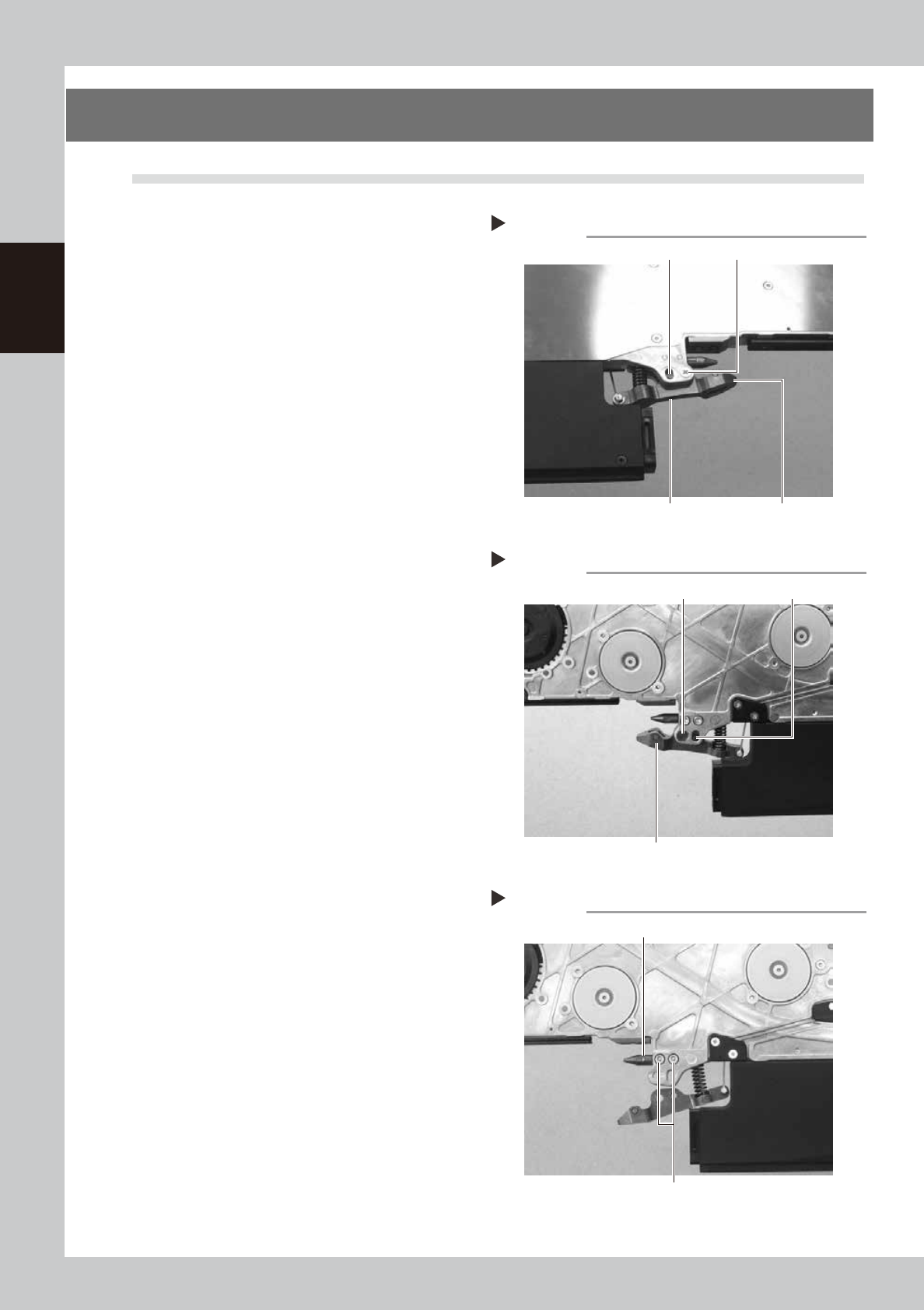
Remove the clamping pin.
Remove the screw securing the clamping
lever assembly main axis with a Phillips
screwdriver (No. 2) and remove the
clamping pin by inserting a hexagonal
wrench or the like in the thread part.
2
Remove the torque limiter pin.
Loosen the setscrew securing the torque
limiter pin for vertical movement of the
clamping lever assembly with a hexagonal
wrench (1.5) and pull off the torque limiter
pin.
63240-9L-00
63241-9L-00
3
Remove the clamping lever
assembly.
Remove the clamping lever assembly by
pulling off the axis of the unclamping wire.
4
Remove the tail pin.
Remove the two bolts securing the tail pin
with a hexagonal wrench (2.5) and pull off
the tail pin from the body.
63224-9L-00
Removing the clamping pin and torque limiter pin
Step 1–3
Setscrew Clamping lever assembly
Torque limiter pin Screw
Removing the clamping pin and torque limiter pin
Step 1–3
Clamping pin
Clamping lever assembly
Torque limiter pin
Removing the tail pin
Step 4
Bolt
Tail pin
2-15
2
Replacing parts
5
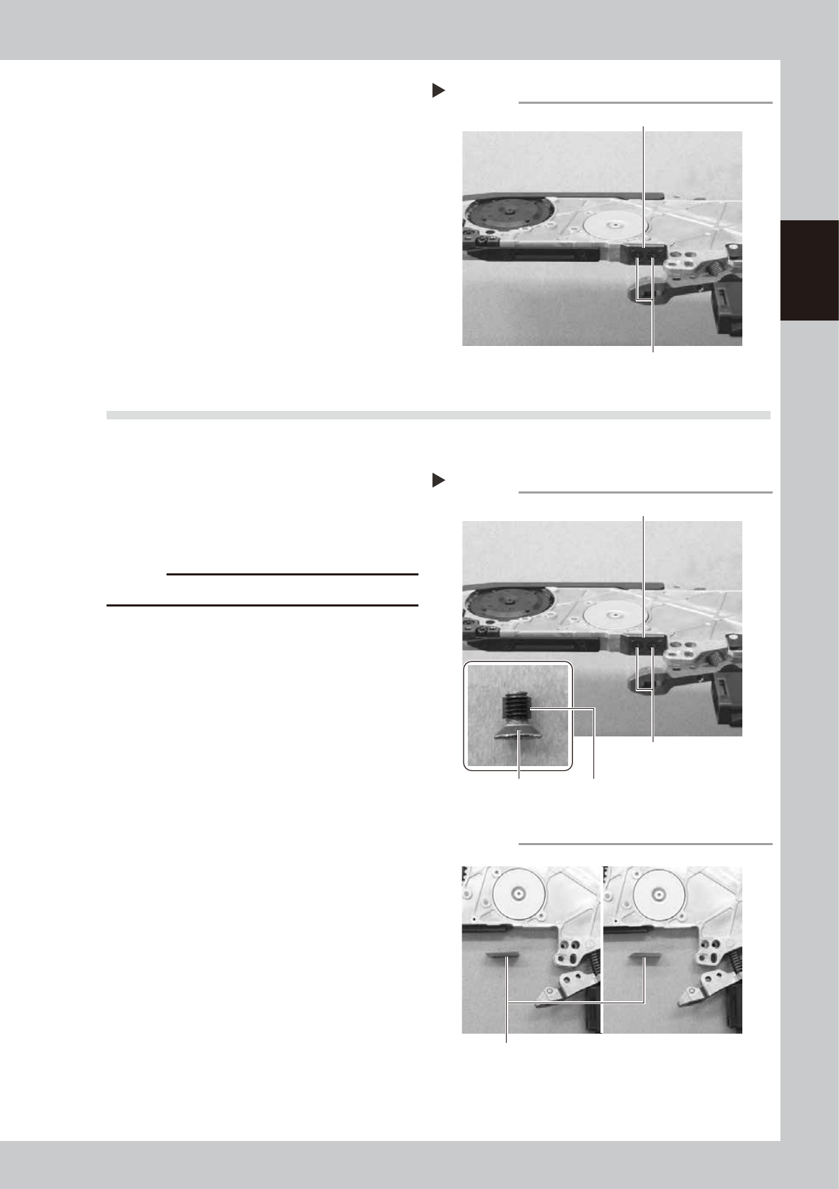
Remove the under plate.
Remove the two screws securing the under
plate with a Phillips screwdriver (No. 2) to
remove the under plate.
63225-9L-00
8.2 Installation
1
Install the under plate.
Apply thread lock (241) to the two screws
and install the new under plate using a
Phillips screwdriver (No. 2).
• Tightening torque: 55N·cm
63226-9L-00
c
CAUTION
Install the under plate in the correct direction.
63260-9L-00
Removing the under plate
Step 5
Screw
Under plate
Installing the under plate
Step 1
Screw
Thread lock (241)
Under plate
Screw
Direction of the under plate
Under plate
OK NG
2-16
2
Replacing parts
2
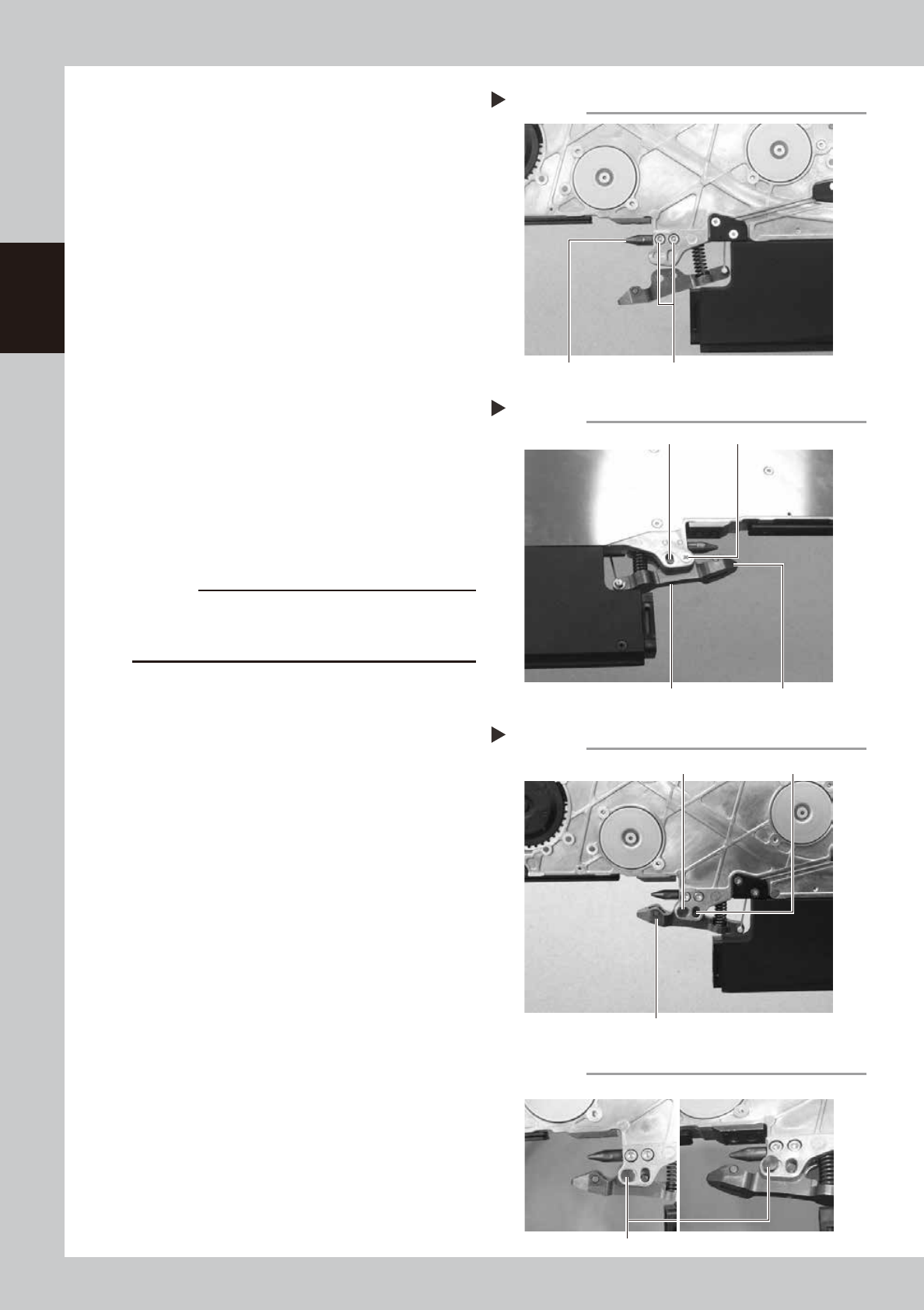
Install the tail pin.
Insert the tail pin into the body aligning the
installation hole, and secure it by tightening
the two bolts using the hexagonal wrench
(2.5).
• Tightening torque: 55N·cm
63227-9L-00
3
Install the clamping lever assembly.
Install the clamping lever assembly to the
body while compressing the spring.
4
Install the torque limiter pin.
Insert the torque limiter pin for vertical
movement and secure it by tightening the
setscrew with a hexagonal wrench (1.5).
• Tightening torque: 40N·cm
5
Install the clamping pin.
Insert the clamping pin from the body and
secure the screw with the Phillips screwdriver
(No. 2).
• Tightening torque: 55N·cm
63230-9L-00
63231-9L-00
c
CAUTION
Both the upper and lower body contact surfaces of the
clamping pin are machined. Fit the surfaces so that the
clamping pin is closely fitted onto the body.
63261-9L-00
Installing the tail pin
Step 2
BoltTail pin
Installing the clamping pin and torque limiter pin
Step 3–5
Setscrew Clamping lever assembly
Torque limiter pin Screw
Installing the clamping pin and torque limiter pin
Step 3–5
Clamping pin
Clamping lever assembly
Torque limiter pin
Clamping pin body contact surface
Clamping pin
OK NG