c921199.R00_EN.pdf - 第55页
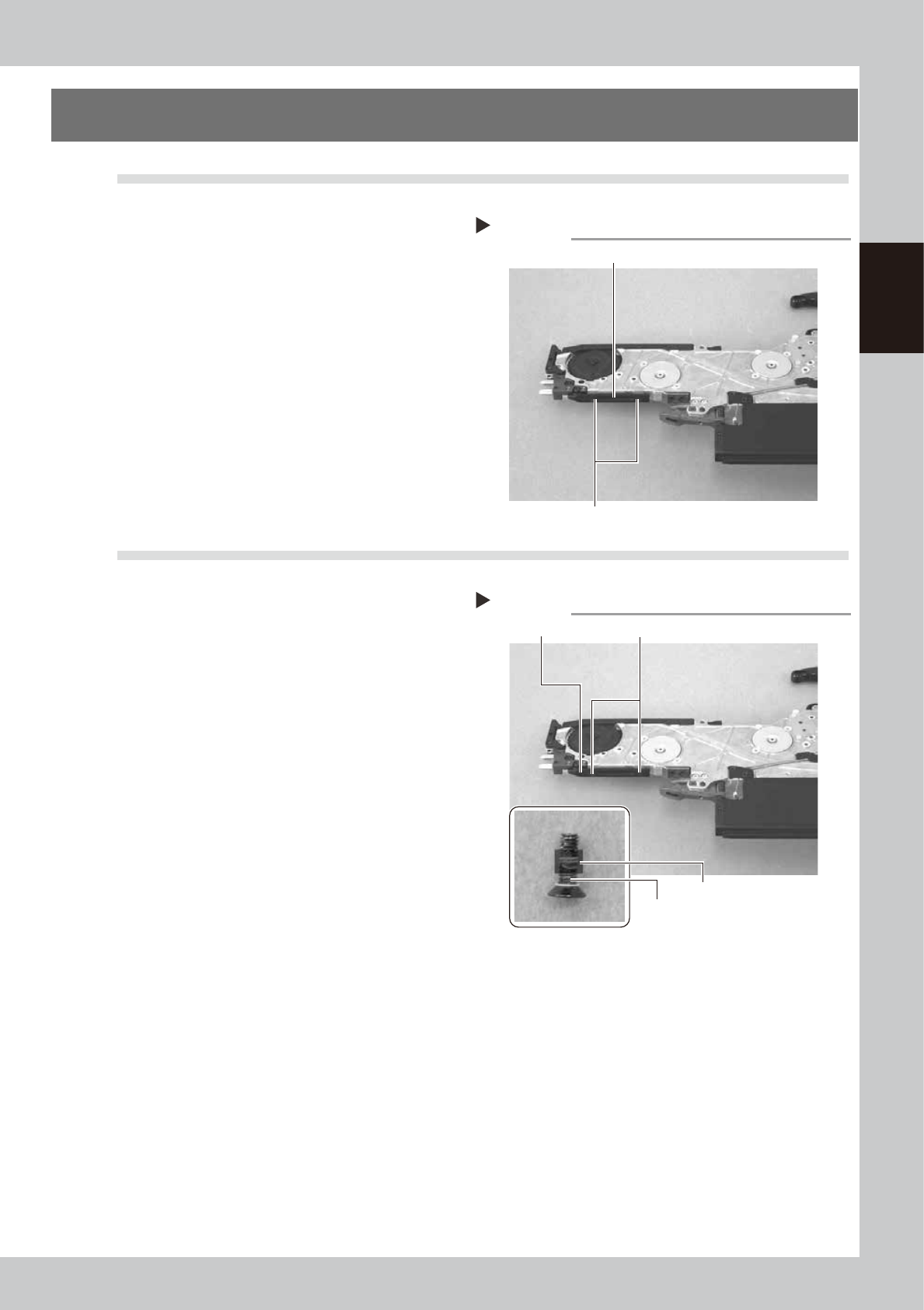
2-9 2 Replacing parts 5. Under rail 5.1 Removal 1 Remo ve the under rail. Remove the two screws securing the under rail with a Phillips screwdriver (No. 1) to remove the under rail. 63212-9L-10 5.2 Installation 1 Install…
2-8
2
Replacing parts
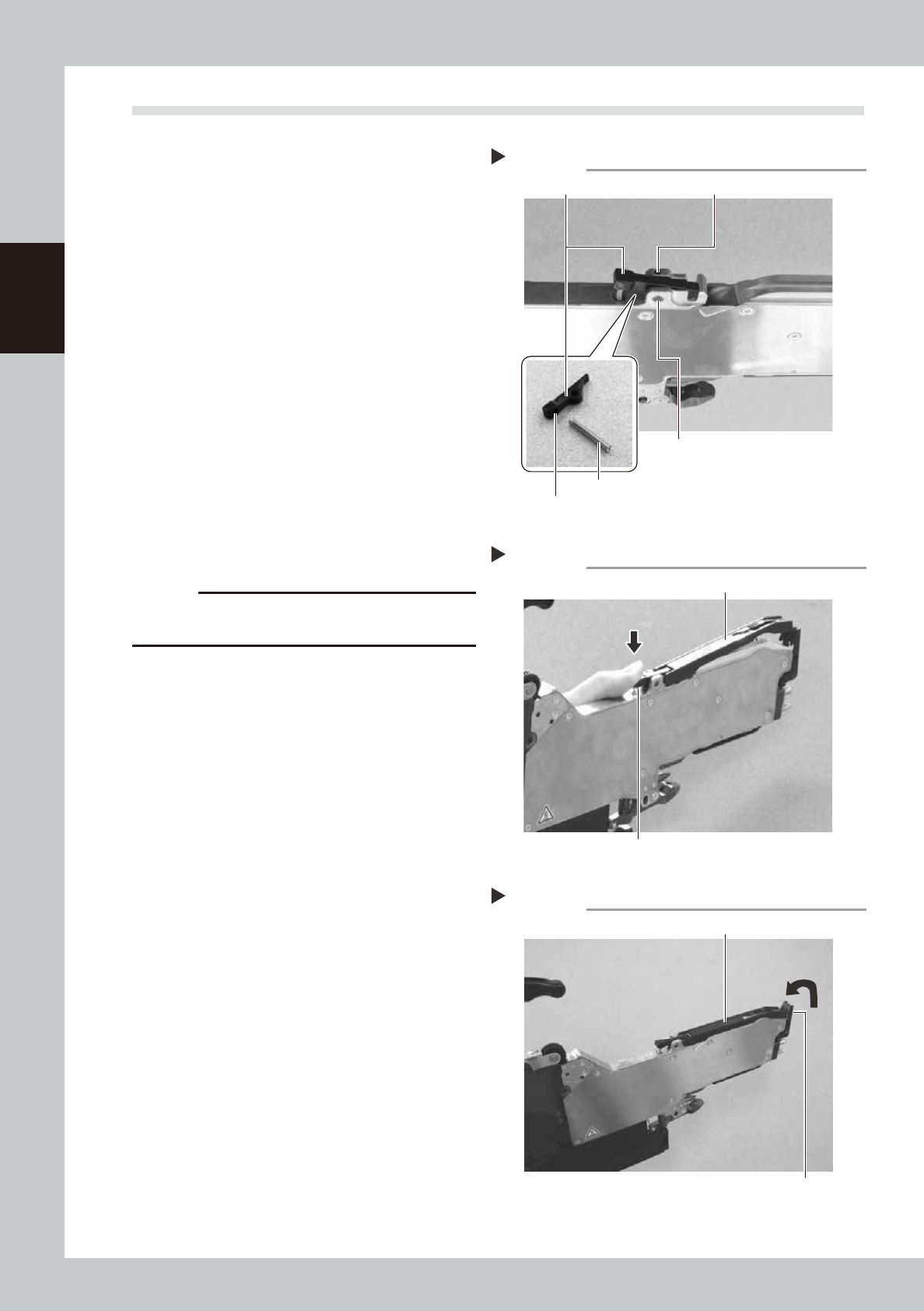
4.2 Installation
1
Install the tape guide rear lever.
Insert the spring on the depressed portion of
the new tape guide rear lever and the
depressed portion of the body, align the
position of the pin insertion hole of the body
and the pin insertion hole of the tape guide
front lever while holding down the tape
guide rear lever, insert the shaft and tighten
the setscrew using the hexagonal wrench
(1.5) to secure the pin.
• Tightening torque: 40N·cm
63211-9L-00
2
Install the tape guide assembly.
Push down the tape guide rear lever and
install the tape guide assembly to the body.
63208-9L-10
3
Secure the tape guide assembly.
Push down the tape guide assembly and
check that it is locked with the tape guide
front lever.
63209-9L-10
c
CAUTION
Check that the sprocket assembly does not interfere
with the tape guide assembly after the installation.
Step 3
Installing the tape guide assembly
Tape guide rear lever
Tape guide assembly
Step 4
Installing the tape guide assembly
Tape guide front lever
Tape guide assembly
Installing the tape guide rear lever
Step 1
Depressed portion
Spring
Tape guide rear lever Setscrew
Shaft
2-9
2
Replacing parts
5. Under rail
5.1 Removal
1
Remove the under rail.
Remove the two screws securing the under
rail with a Phillips screwdriver (No. 1) to
remove the under rail.
63212-9L-10
5.2 Installation
1
Install the under rail.
Apply thread lock (241) to the two screws
and install the new under rail using the
Phillips screwdriver (No. 1).
• Tightening torque: 30N·cm
63213-9L-10
Step 1
Removing the under rail
Screw
Under rail
Step 1
Installing the under rail
Under rail Screw
Thread lock (241)
Screw
2-10
2
Replacing parts
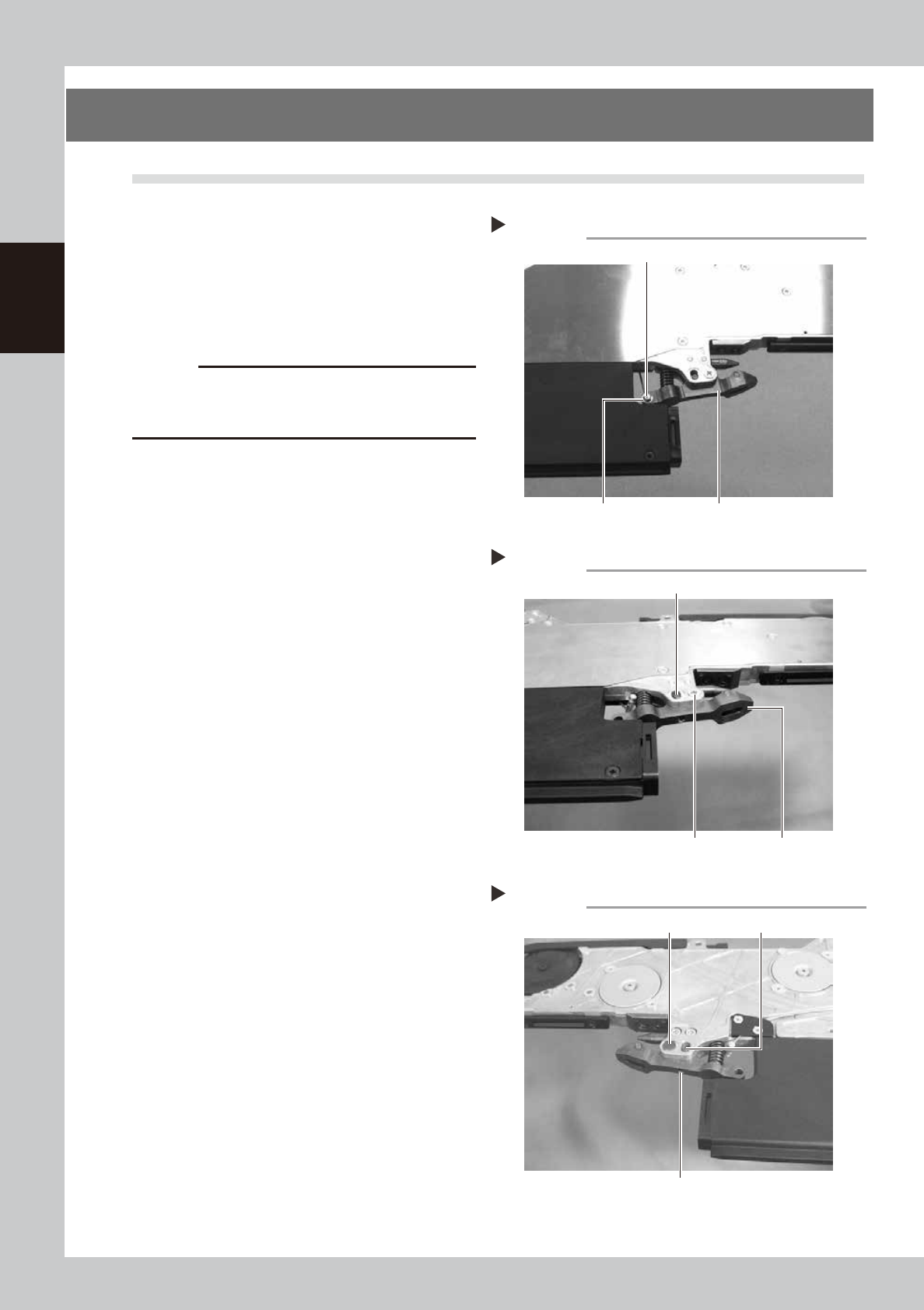
6. Clamping lever assembly
6.1 Removal
1
Remove the axis of the unclamping
wire.
Remove the E-ring of the unclamping wire
attached to the clamping lever assembly
with a precision screwdriver (flat-blade) and
remove the axis of the unclamping wire.
63214-9L-00
c
CAUTION
· When removing the E-ring, pay attention not to lose it.
· The E-ring is an exclusive part. If it should be lost, do
not use any E-ring other than the specified one.
2
Remove the clamping pin.
Remove the screw securing the clamping
lever assembly main axis with a Phillips
screwdriver (No. 2) and remove the
clamping pin by inserting a hexagonal
wrench or the like in the thread part.
3
Remove the torque limiter pin.
Loosen the setscrew securing the torque
limiter pin for vertical movement of the
clamping lever assembly with a hexagonal
wrench (1.5) and pull off the torque limiter
pin.
63215-9L-00
63216-9L-00
4
Remove the clamping lever
assembly.
Remove the clamping lever assembly.
Removing the axis of the unclamping wire
Step 1
Clamping lever assemblyE-ring
Axis of the unclamping wire
Removing the clamping pin and torque limiter pin
Step 2, 3
Screw Clamping lever assembly
Torque limiter pin
Removing the clamping pin and torque limiter pin
Step 2, 3
Setscrew
Clamping pin
Torque limiter pin