c921199.R00_EN.pdf - 第70页
2-24 2 Replacing parts 2 Install the unclamping wire. Insert the unclamping wire from the handle mounting portion side. 63246-9L-00 3 Install the tension spacer 1, tension spacer 2, wire tension 1 and tension spring. Ins…
2-23
2
Replacing parts
4
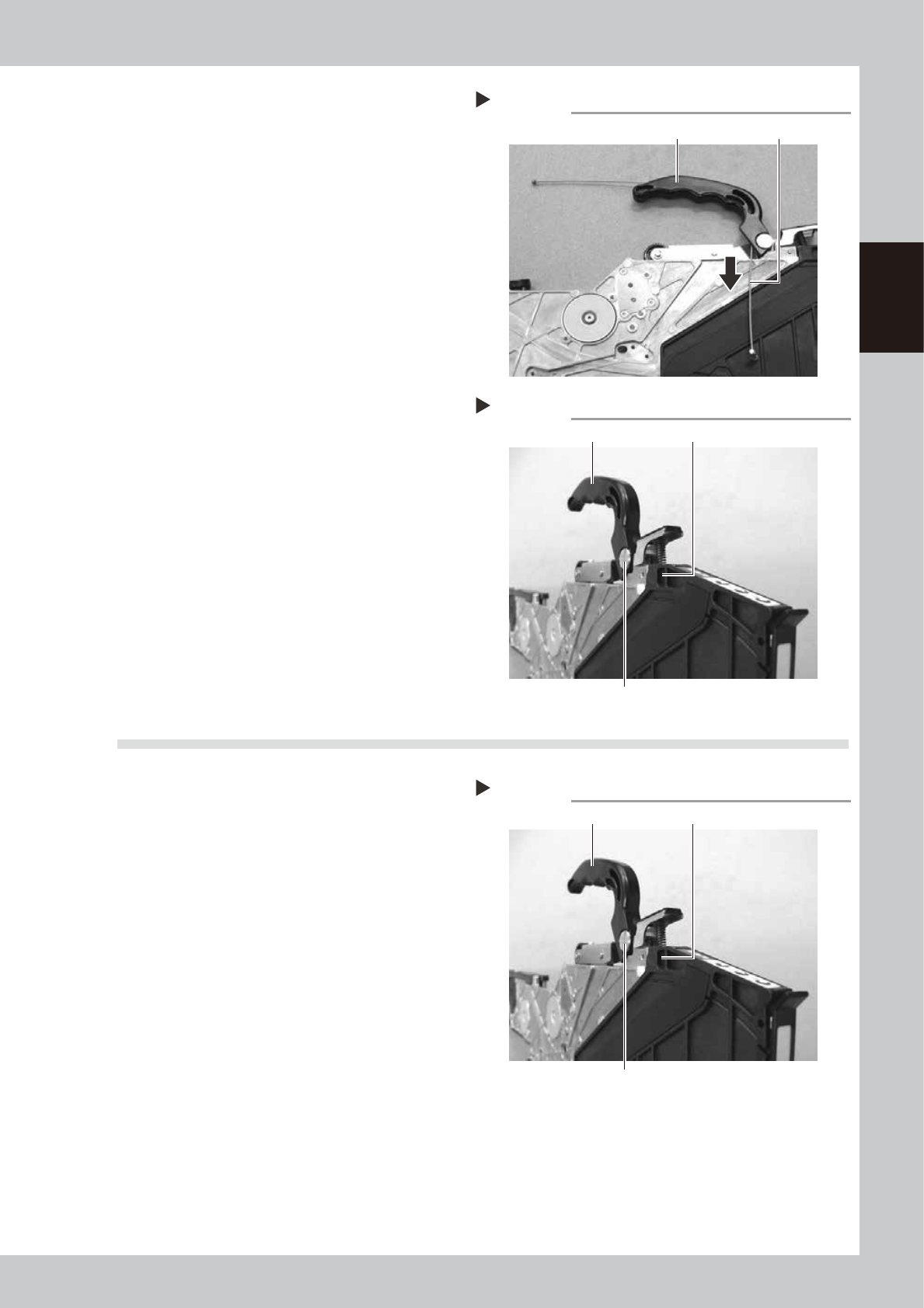
Remove the unclamping wire.
Pull out the unclamping wire from the
handle mounting portion side.
63234-9L-00
5
Remove the handle.
Remove the setscrew securing the handle
pin with a hexagonal wrench (1.5), pull out
the handle pin and remove the handle.
63244-9L-00
11.2 Installation
1
Install the handle.
Install the new handle, insert the handle pin,
apply the thread lock (241) and then secure
the handle by tightening the setscrew using
the hexagonal wrench (1.5).
• Tightening torque: 40N·cm
63245-9L-00
Removing the unclamping wire
Step 4
Handle Unclamping wire
Removing the handle
Step 5
Handle
Handle pin
Setscrew
Installing the handle
Step 1
Handle Setscrew
Handle pin
2-24
2
Replacing parts
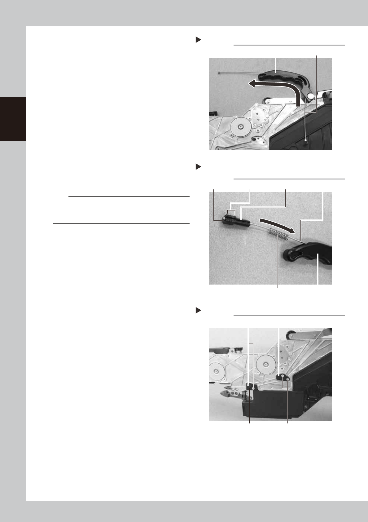
2
Install the unclamping wire.
Insert the unclamping wire from the handle
mounting portion side.
63246-9L-00
3
Install the tension spacer 1, tension
spacer 2, wire tension 1 and tension
spring.
Install the tension spacer 1, tension spacer 2
(some pieces), wire tension 1 and tension
spring at the tip of the unclamping wire and
put in the handle.
63247-9L-00
4
Install the wire covers 1 and 2.
Install the respective wire covers by
tightening the two screws with a Phillips
screwdriver (No. 1).
• Tightening torque: 30N·cm
63248-9L-00
n
NOTE
The wire covers 1 and 2 have grooves for passing a wire
on the back side. Be sure to pass the wire in the
grooves.
Installing the unclamping wire
Step 2
Handle Unclamping wire
Step 3
Installing the tension spacers 1 and 2,
wire tension 1 and tension spring
Tension spring
Wire tension 1 Tension spacer 1 Unclamping wireTension spacer 2
Handle
Installing the wire covers 1 and 2
Step 4
Wire cover 1 Screw
Wire cover 2Screw
2-25
2
Replacing parts
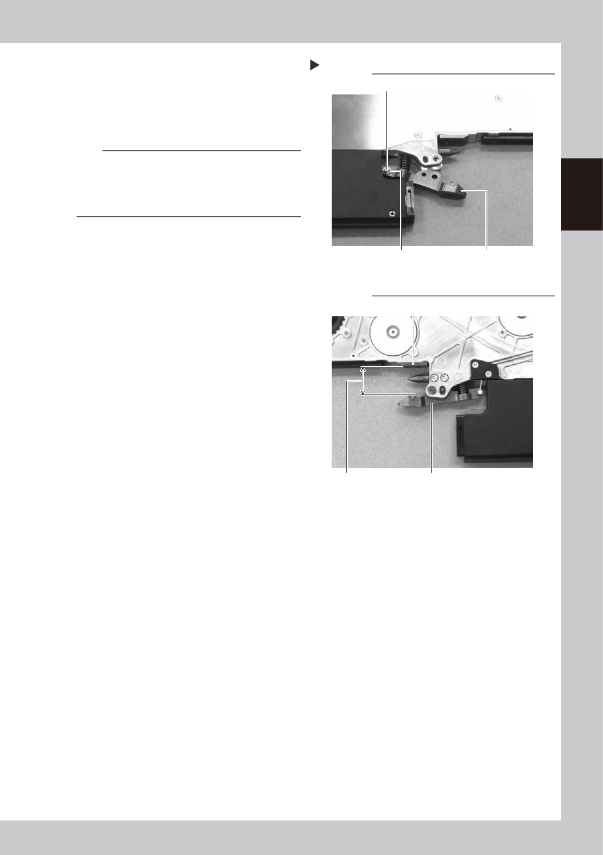
5
Install the axis of the unclamping
wire.
Pass the axis of the unclamping wire into the
clamping lever assembly, install the E-ring
and secure the E-ring with longnose pliers.
63249-9L-00
n
NOTE
Check that the distance between the under plate and
the clamping lever assembly is 20 to 21 mm when the
handle is opened. If the distance is out of the range,
adjust the distance by changing the number of the
tension spacer 2.
63239-9L-00
Installing the axis of the unclamping wire
Step 5
E-ring
Axis of the unclamping wire
Clamping lever assembly
Checking the distance
Under plate
20 – 21mm
Clamping lever assembly