444CEOM1-CM202.pdf - 第101页
Page 3-3 FUNCTIONS 3 444C-E-OMA03-A01-02 3-1-2 Engineer Mode Menu Configuration Engineer Data modify Describes customizing the functions of the oper ator mode. 3-5-5 Customizing Operator Mode Describes setting the time o…
Page 3-2
444C-E-OMA03-A01-01
3-1 Menu Configuration
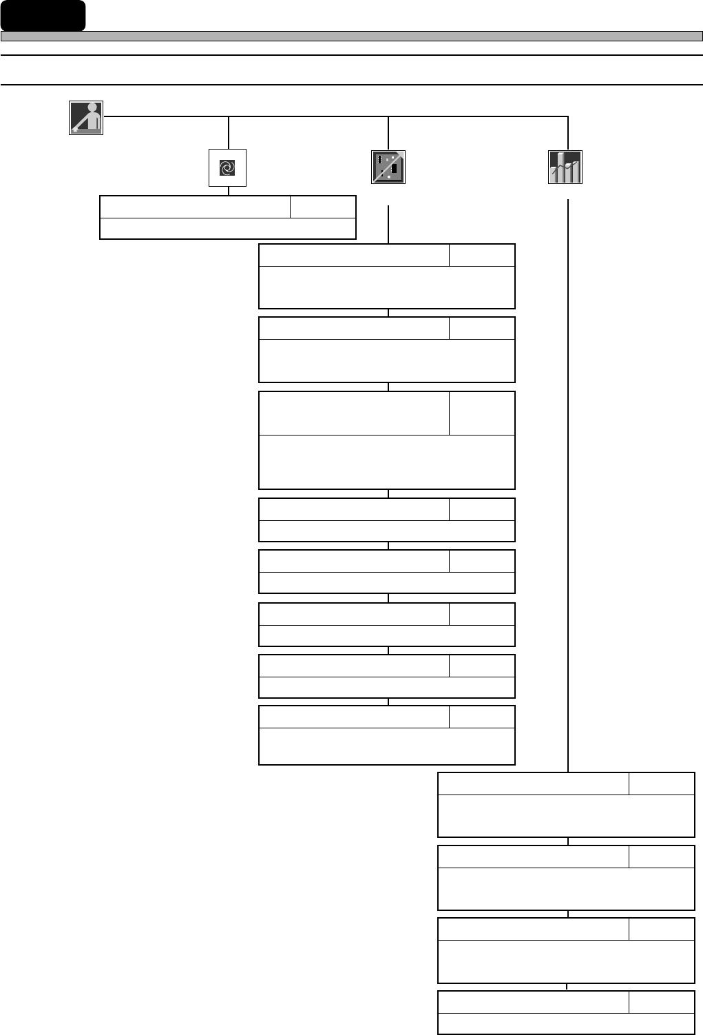
3-1-1 Operator Mode
Operator
Production
Describes starting automatic production.
Chapter 4PRODUCTION
Describes resetting production information.
3-3-4Reset
Describes checking the nozzle arrange-
ment of head.
3-2-1Nozzle Settings
Describes checking board transport motion.
3-2-4Board Transport
Describes checking feeder arrangement.
3-2-5Feeder Arrangement
Describes changing board supports.
3-2-6Changing Support Pins
Describes displaying the information
during running.
3-3-1Run Information
Describes calculating the consumption
of chips to the count of production
boards and setting the timing to cut tape.
3-2-3
Calculating Chip Consumption
/ Setting Tape Cut Timing
Displays the chip pick-up information
during production.
3-3-3Pick-up Information
Describes displaying the factors that made
the machine stop during production.
3-3-2Stop Information
Performance
info
Product
config
Describes setting the mobile table for the
exchange mode.
3-2-2Selecting Table Mode
Describes setting each motion.
3-2-7Motion Setup
Describes cutting off the vacuum to the
nozzles.
3-2-8Vacuum OFF
Page 3-3
FUNCTIONS
3
444C-E-OMA03-A01-02
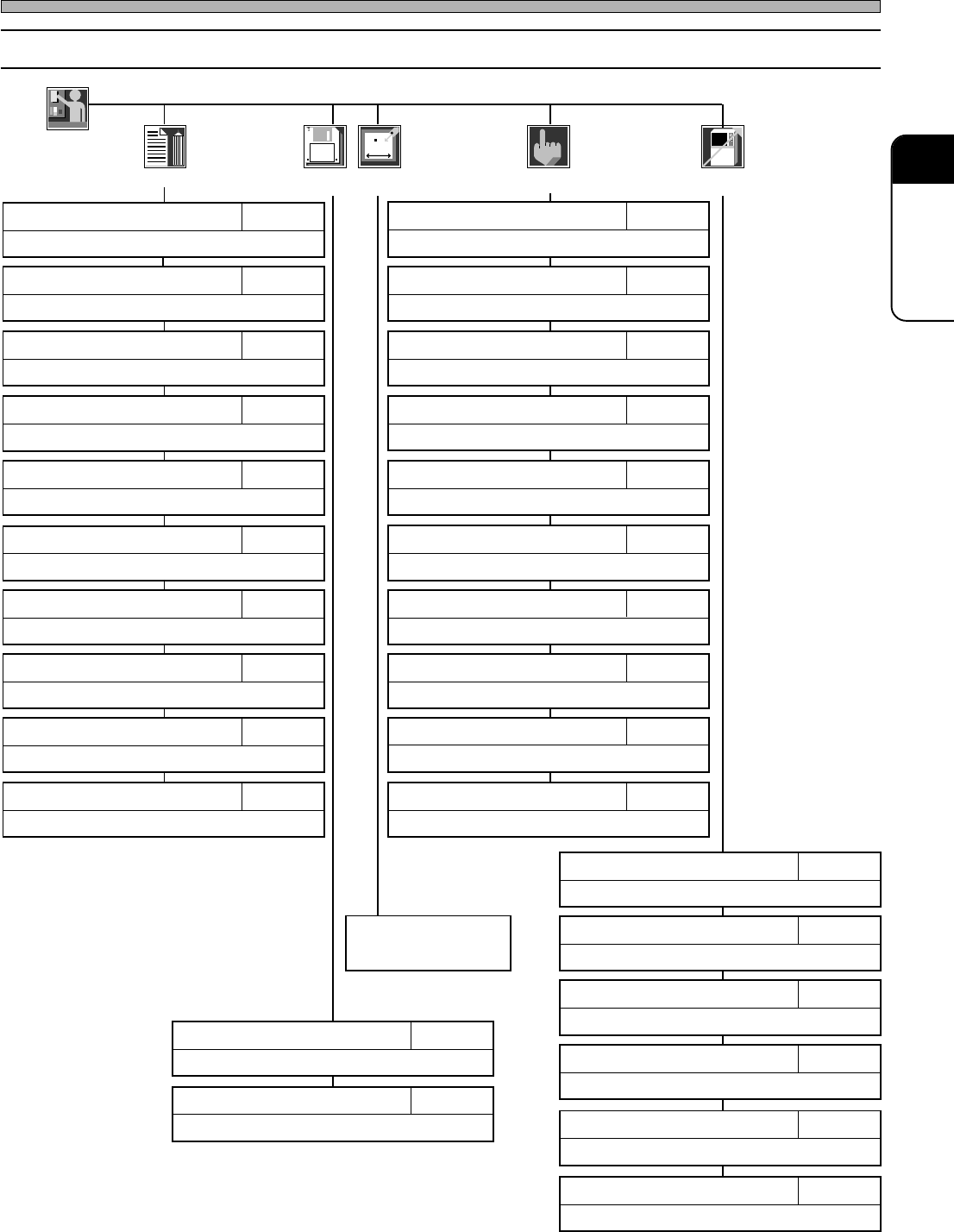
3-1-2 Engineer Mode
Menu Configuration
Engineer
Data modify
Describes customizing the functions of the operator mode.
3-5-5Customizing Operator Mode
Describes setting the time of the machine.
3-5-4Setting Time
Describes specifying and resetting defective nozzles.
3-5-3Defective Nozzle
Describes displaying the input addresses in bit.
3-4-6Input Check
Describes checking recognition processing motion.
APPENDIX A
RECOGNITION DEVICE
Describes checking nozzle stock data.
7-7Nozzle Stock Data
Describes checking and modifying mount data.
7-9Mount Data
Describes checking production data.
7-11Library Display
Describes checking and modifying board data.
7-2PCB Data
Describes checking nozzle arrangement data.
7-6Nozzle Arrangement Data
Describes teaching production data.
Chapter 8TEACHING
Describes returning all axes to their origins.
3-4-1Returning to Origin
Describes adjusting the width of conveyor.
3-4-2Conveyor Width Adjustment
Describes transporting board onto conveyor.
3-4-3Board Transport
Describes changing nozzles.
3-4-4Nozzle Changing (Option)
Describes displaying the load onto ring.
3-4-10Ring Load Information
Describes checking the state of valve and working it.
3-4-7Output Check
Describes checking and modifying board recognition data.
7-3Board Recognition Data
Describes checking feeder layout list and stock data.
7-4Feeder Layout / Stock Data
Describes checking the settings of function switches.
7-10Function Switch
Describes checking and modifying block attribute data.
7-8Block Attribute Data
Describes checking the current positions and states of all axes.
3-4-8Axis Information
Describes pick-up, recognition and mounting motions.
3-4-5Pick-up and Mounting Motions
Describes checking the correction value by pick-up position learning.
3-5-2Pick-up Position Learning
Describes changing the conditions for the motions for production.
3-5-1Switches for Adjustment
Describes loading/saving machine parameters.
Chapter 6Sub operation
Describes loading production data.
Chapter 6Main operation
Refer to the mainte-
nance manual.
File
managment
Machine
parameter
Machine
config
Machine
adjust
Describes setting the backlight-off time.
3-5-6Setting Backlight
Page 3-4
444C-E-OMA03-A01-05
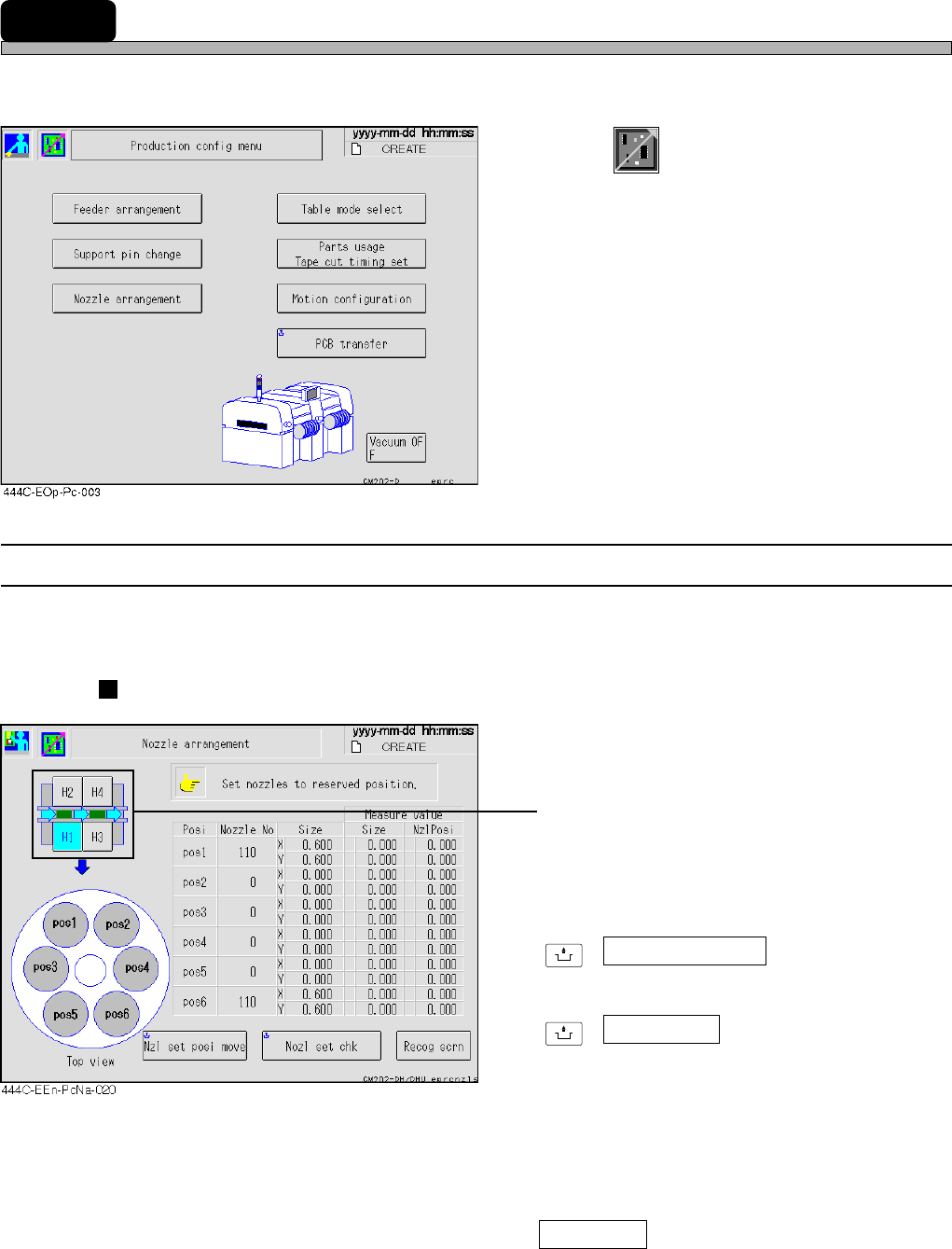
3-2 Production Settings
This is used for the settings requisite for production and to check the motion.
1. Press
Product
config
on the main menu.
• “Production config menu” is displayed.
∗ Pressing a function switch displays each
setting screen.
3-2-1 Nozzle Settings
You can check the nozzle arrangement of each head. The names of the nozzles attached to each
head now are displayed.
Without nozzle changer
• Press the head you would like to check.
(CM201 has only the stage A.)
∗ For information about how to change nozzles,
see “9-4 Nozzle Exchange”.
UNLOCK
+ Nzl set posi move
Moves head to the nozzle setting position.
UNLOCK
+ Nozl set chk
Recognizes whether the nozzles have been
attached correctly and displays the measured
values (nozzle diameter, nozzle inclination).
As for the nozzle position that has no nozzles
or before recognizing nozzles, 0.0 is displayed.
If they have been attached incorrectly, the
warning message appears.
Recog scrn
Displays the recognition image at when the
nozzle setting check was performed.