444CEOM1-CM202.pdf - 第120页
Page 3-22 Machine Adjustment 3-4-8 Axis Information This is used to check the current positions of all the axes the machine controls and the status information. Current pos cnt Displays the current position of each axis …
Page 3-21
FUNCTIONS
3
Machine Adjustment
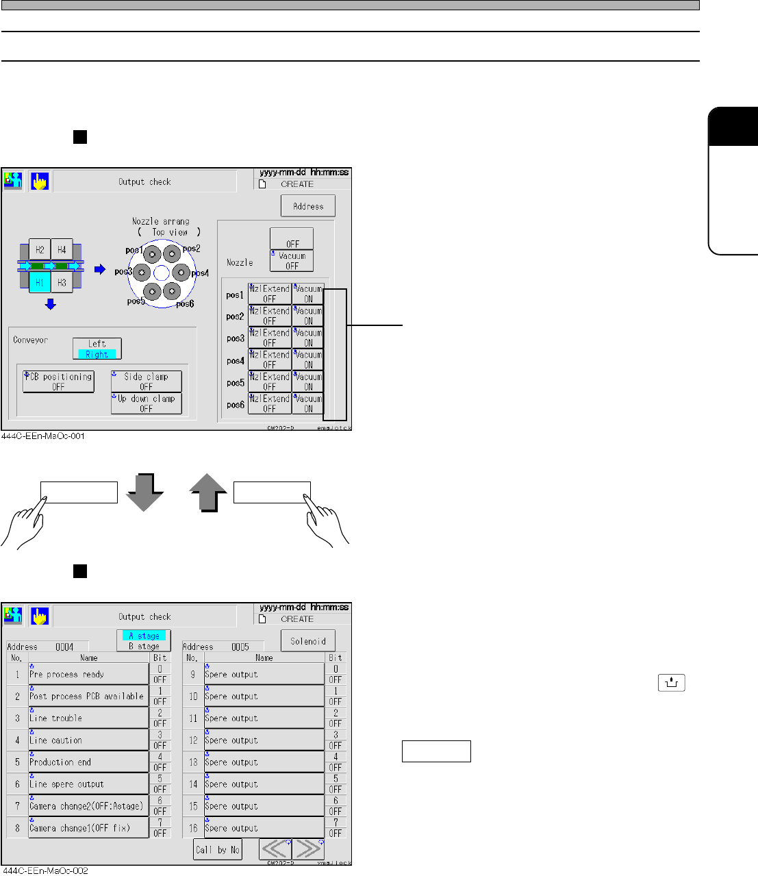
3-4-7 Output Check
This is used to check the states of the valves which are used frequently in adjustment for each
stage and work each of them alone.
Solenoid display
Nozzle
You can work each valve of compulsory blow,
vacuum and letting the nozzle out.
Conveyor
You can work the board positioning of the
board holder, side clamp and upper/lower
clamp.
Display for each address
• The states of the output addresses the ma-
chine uses are displayed with names for each
bit.
Highlighted name shows its bit is ON (1).
When you press the “Name” button with
UNLOCK
pressed, the signal opposite to the current
state is output and displayed again.
Call by No
Displays the address that includes the speci-
fied No. at the left side of screen.
444C-E-OMA03-A01-06
Address Solenoid
∗ For CM201-D/DU/DH or CM202-D/DU/DH/
DHU, this is an option.
Indicates the current values of the vacuum
sensor.
Page 3-22
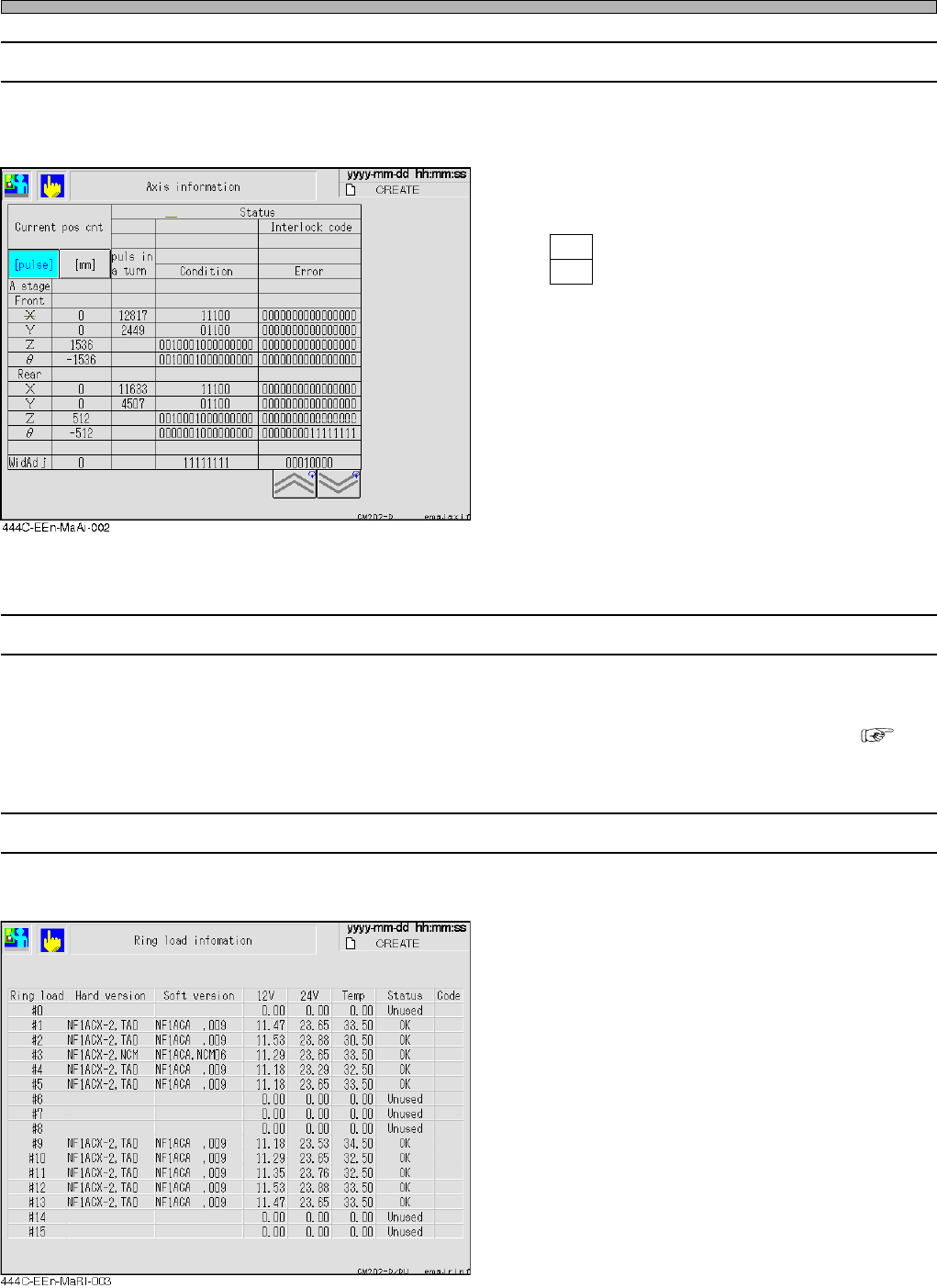
Machine Adjustment
3-4-8 Axis Information
This is used to check the current positions of all the axes the machine controls and the status
information.
Current pos cnt
Displays the current position of each axis in
mm or pulse of status address.
pls : Displays the current position in pulse.
mm : Displays the current position in mm.
Status
Displays the state of status address, error/busy
of each axis, in bit.
pulse in a turn
This data is sampled and displayed against X-
and Y-axes only.
<Meaning of abbreviation>
X : X-axis of X-Y unit
Y : Y-axis of X-Y unit
Z : Z-axis
θ
:
θ
-axis
3-4-9 Recognition Device Maintenance
This is used to check all the recognition processing motions.
∗ For information about how to operate it, refer to “Appendix A RECOGNITION DEVICE” ( A-5
Recognition Device Maintenance).
3-4-10 Ring Load Information
This is used to display the load onto ring.
444C-E-OMA03-A01-03
Page 3-23
FUNCTIONS
3
3-5 Machine Settings
This is used to set the state of machine that does not depend on production data.
∗ On the main menu (default state) in the operator mode, you cannot select this function.
1. Press
Machine
config
on the main menu.
•“Machine configuration menu” is displayed.
∗ Pressing a switch displays each setting screen.
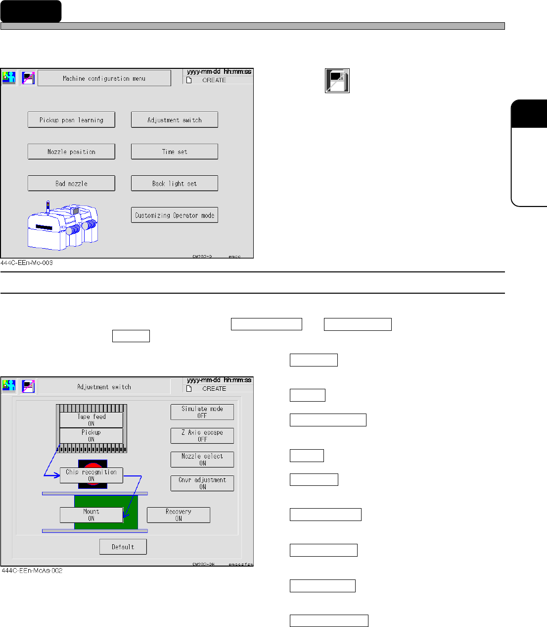
3-5-1 Switches for Adjustment
You can change the conditions of production motion for adjustment temporarily.
Usually, all the items are ON except Simulate mode and Z Axis escape .
Pressing Default or restarting the machine returns the settings to the usual ones.
Tape feed
When it is ON, tape feeding by the feeder is
enabled.
Pickup
When it is ON, pick-up motion is enabled.
Chip recognition
When it is ON, chip recognition and error check
is enabled.
Mount
When it is ON, mounting motion is enabled.
Recovery
When it is ON, re-pickup of the pick-up error
and recognition error chips is enabled.
Simulate mode
When it is ON, the repeated operation of
production data is enabled.
Z Axis escape
When it is ON, the operation with Z-axis
retracted at the fixed height is enabled.
Nozzle select
When it is ON, the up-and-down motion by
nozzle selection is enabled.
Cnvr adjustment
When it is ON, a width adjustment is made.
When it is OFF, a width adjustment is not
made.
444C-E-OMA03-A01-05