444CEOM1-CM202.pdf - 第108页
Page 3-10 444C-E-OMA03-A01-02 Production Settings Occupancy Occupancy Pressing this switch displays the screen as shown left. The state of physical occupancy of table is displayed. (CM201 has the table No. 1 and 2 only .…
Page 3-9
FUNCTIONS
3
444C-E-OMA03-A01-05
Production Settings
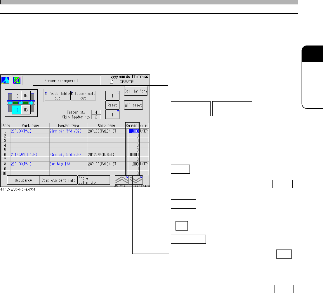
3-2-5 Feeder Arrangement
You can check which chip is on which feeder address.
First, check the state of the feeders arranged on the stage.
• The information of the chips on each feeder is displayed in the order of feeder address. Through
the state of occupancy, you can see which feeder address on the feeder table is used at a glance.
The number of the residual chips on each reel is also displayed.
• Select the feeder table you will check.
(CM201 has only the stage A.)
Draws out the selected feeder table. Pressing
the switch again returns the feeder table where
it was.
Reset
Resets the number of the residual chips
pointed by a cursor now. (Pressing ↑ and ↓
moves a cursor up and down.)
All reset
Resets the number of the residual chips on all
the feeders. When the message appears, press
Yes .
Call by Adrs
Pressing this switch displays the input screen.
When you enter an address and press ENT ,
a cursor moves to the specified address.
∗ When the remaining chip count is “0”, a yellow
mark lights up in this field. Check the feeder
and replace the workpieces. Pressing Reset
will reset the remaining count and delete the
yellow lit.
L feeder Table
out
R feeder Table
out
∗ For CM201-DS or CM202-DS, the feeder table
draw-out function is an option.
Page 3-10
444C-E-OMA03-A01-02
Production Settings
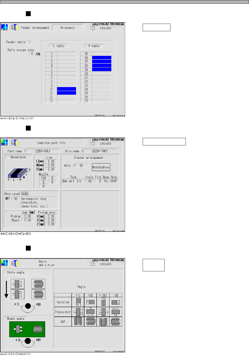
Occupancy
Occupancy
Pressing this switch displays the screen as
shown left.
The state of physical occupancy of table is
displayed.
(CM201 has the table No. 1 and 2 only.)
Comprehensive parts information
Complete part info
Pressing this switch displays the screen as
shown left.
The comprehensive information of parts
including the chip information of the feeder
pointed by a cursor is displayed.
∗ Move a cursor to the address you would like
to display, then press this switch.
Angle definition
Angle
definition
Pressing this switch displays the screen as
shown left.
The angle definition of the main chips in picking
up and mounting is displayed.
Page 3-11
FUNCTIONS
3
444C-E-OMA03-A01-05
Production Settings
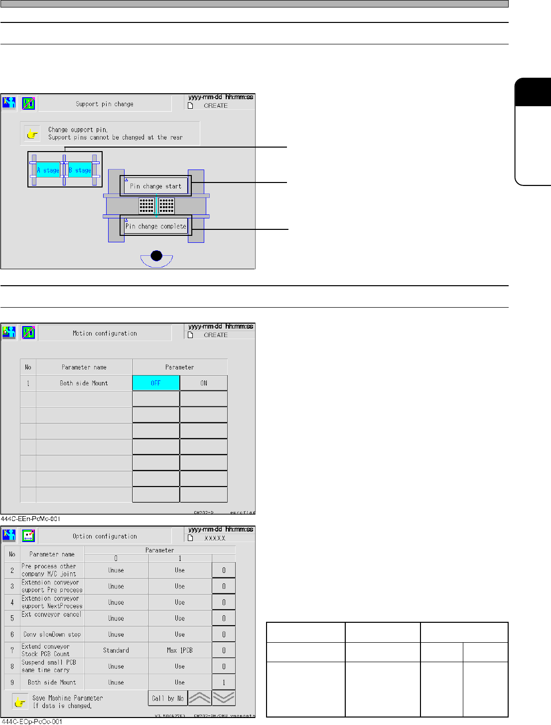
3-2-6 Changing Support Pins
This part describes changing support pins together with board support blocks.
• For detailed information about how to change them, see “9-3 Setting the Support Pin”.
• Select the stage on which the support pins will
be exchanged. (CM202 only)
• Board support blocks rise up so that you can
draw out them.
• Board support blocks lower.
3-2-7 Motion Setup
• Select ON or OFF.
Both side Mount
When mounting the board whose reverse side
have already been mounted, set this to ON.
Enabling this function provides the following
changes.
1. For the small board transport, when the
stopper is raised, it may interfere with the
chips on the reverse side. Therefore, the
maximum length of the small board will be
changed from 215 mm to 195 mm.
(CM201-D/DU, CM202-D/DU only)
2. When the board is ejected after mounted,
the support pins may interfere with the
chips on the reverse side. Therefore, the
board will be ejected after checking the
board holder has lowered.
444C-EEn-PcSp-002
However, when both-side mounting is set to
“Use (1)” at the option configuration screen as
shown left, the motion configuration screen no
longer displays this item.
Option configuration Enabled Disabled
Motion configuration The item is hidden Enabled Disabled
Transport operation
Both-side
mounting
is Disabled
Both-side
mounting
is enabled
Both-side
mounting
is enabled