444CEOM1-CM202.pdf - 第71页
Page 1-9 GENERAL DESCRIPTION 1 444C-E-OMA01-A01-00 Names and Mechanism of Each Unit Recognition camera This machine has two types of recognition camer a: head camera and line camera. a) Head camera The head camera is set…
Page 1-8
444C-E-OMA01-A01-02
Names and Mechanism of Each Unit
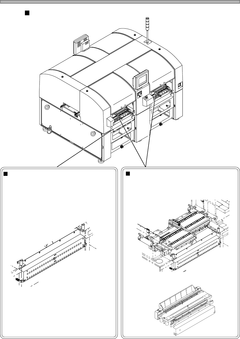
Chip feeding units
Tape feeder table
(CM201: Two in total / CM202: Four in total)
This is the table where tape feeders will be set. It
moves the feeders through the air cylinder.
Bulk feeder supporting unit
(option)
This is the unit to support bulk feeders. It has the
compressed (pressure-governed) air coupler and
electric-signal connectors to drive the bulk feeders.
4U4C-AA00
150FC0AA
150FC0AA
∗ For CM201-DS or CM202-DS, this is an option.
∗ Standard for CM201-DS or CM202-DS
(Fixed feeder table)
E24C-413E
Page 1-9
GENERAL DESCRIPTION
1
444C-E-OMA01-A01-00
Names and Mechanism of Each Unit
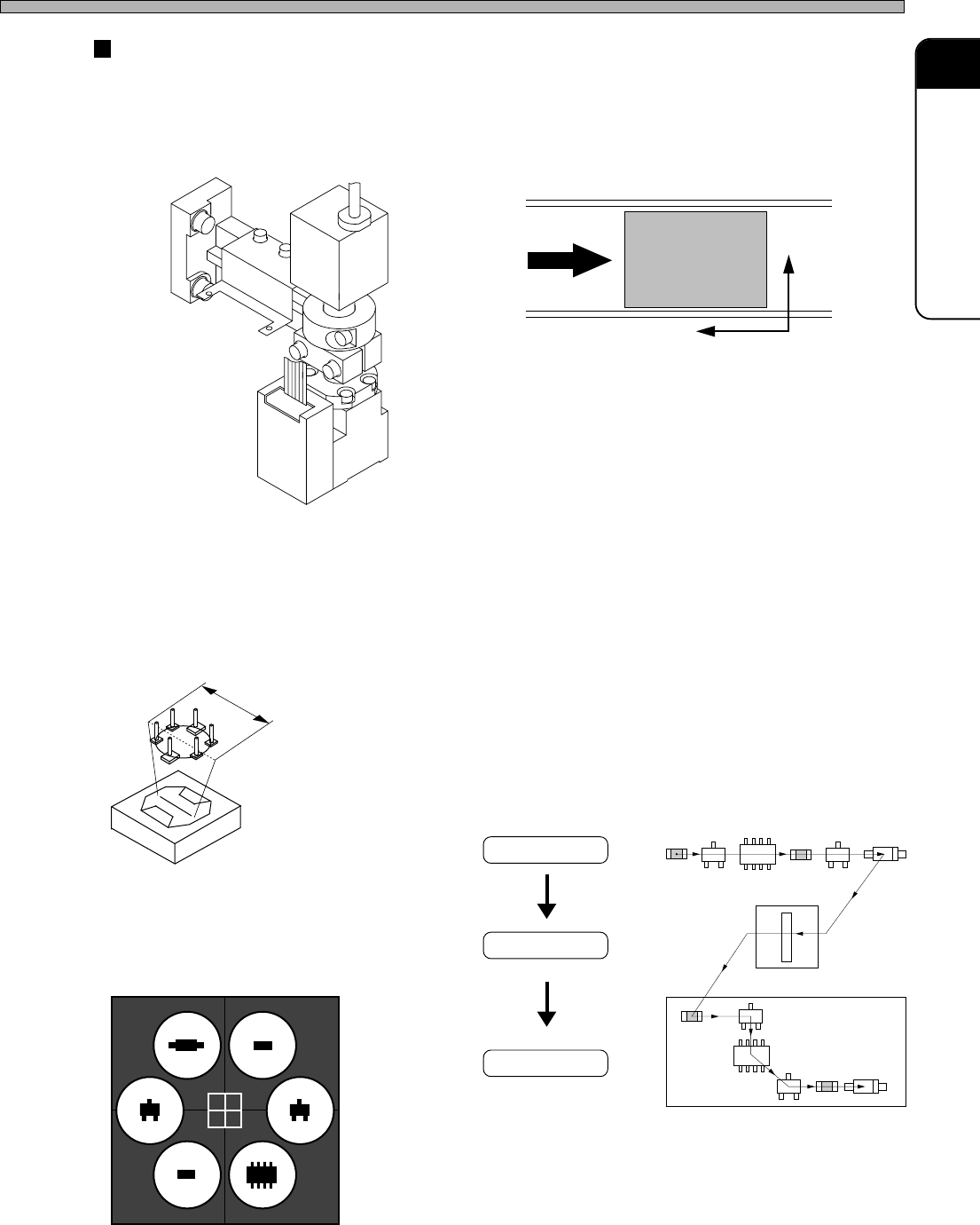
Recognition camera
This machine has two types of recognition camera: head camera and line camera.
a) Head camera
The head camera is set on the head unit, and recognizes the precise position of board.
b) Line camera
The line camera is set on the frame of main body, and recognizes chips (positioning deviation,
inclination, chipping, etc.).
Line camera
Board
[Process]
Six chips are scanned and recognized all together by
moving the head so that it will move across the line.
Start
Batch
recognition
444C-104E
Chip pick-up
Line width : 55mm
444C-103E
Recognition
Mounting
Recognition image
Reference position
Board
Y
X
444C-105E
160CC0AA
Page 1-10
444C-E-OMA01-A01-00
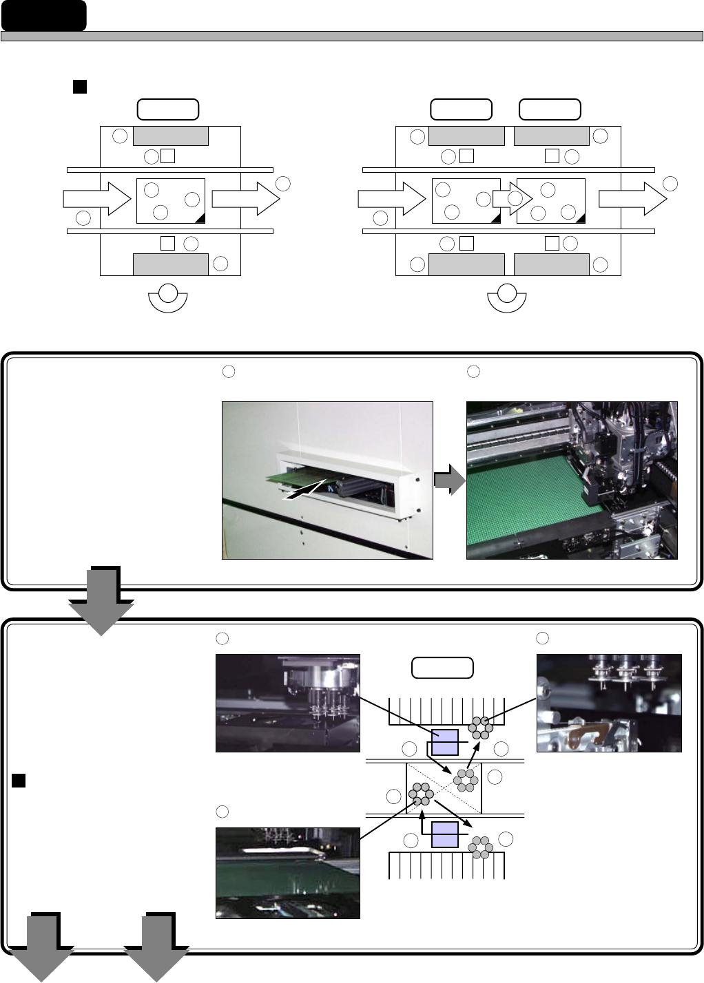
1-2 Mounting Mechanism
This section describes the mounting mechanism in due order.
Mobile parts
1
The board transported in
from the previous process
is set in the board holder
on the stage A.
2
Through the two transfer
heads, chips are mounted
high-speedily.
Alternate mounting
While one head recog-
nizes and mounts chips,
the other head picks up
and recognizes chips.
Transporting
board in
1
A board is transported in from
the previous process.
2
The board is clamped and
recognized.
Mounting chips
To “3 Transferring
board”
To “5 Transporting
board out”
CM202 CM201
444C-106E
CM201 CM202
Stage A Stage A Stage B
Table No. 2 Table No. 2 Table No. 4
From previous process
To next process
Rear side
Front side
To next process
From previous process
Table No. 1
Table No. 1 Table No. 3
3
4
5
5
2
11
3
4
1 1
3
4
5
5
2
10
10
6
8
9
7
11
4
9
3
8
8
3
Picking up chips
444C-105P
444C-107E
Stage A
444C-104P
5
Mounting the chips
444C-110P
4
Recognizing the chips
444C-109P444C-119P
4 3
5
5
4
3