444CEOM1-CM202.pdf - 第133页
Page 3-35 FUNCTIONS 3 444C-E-OMA03-A01-01 Others 3-6-6 Operating Procedure against Pick-up Instability Error If a pick-up instability error is detected, the machine comes to an immediate stop with the chip above the ejec…
Page 3-34
444C-E-OMA03-A01-01
Others
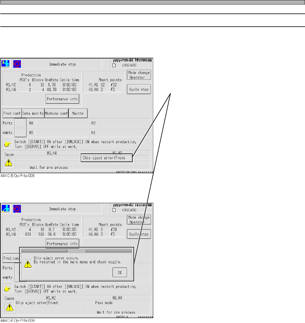
3-6-5 Operating Procedure against Chip Eject Error
If the machine fails to eject the chip after the operation resumes out of a chip mount
error, it comes to an immediate stop.
• In this case, the chip may be adhered to the
nozzle. Stop the automatic operation to return
to the main menu.
• The automatic operation does not resume if
you try to.
Turn OFF the servo switch.
Check and clean the tip of the nozzle.
Turn ON the servo switch.
• The automatic operation (mounting) resumes.
Page 3-35
FUNCTIONS
3
444C-E-OMA03-A01-01
Others
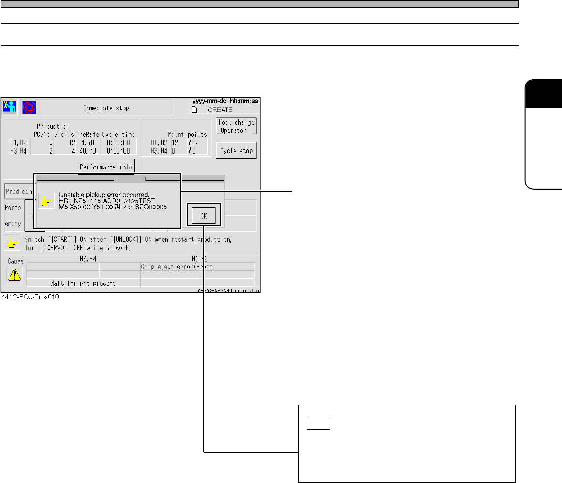
3-6-6 Operating Procedure against Pick-up Instability Error
If a pick-up instability error is detected, the machine comes to an immediate stop with the chip
above the ejection box without mounting it.
• The detailed information appears.
HD1 NP5=115 ADR3=2125TEST
M5 X50.00 Y51.00 BL2 c=SEQ00005
“HD1” : Head number
“NP5” : Nozzle position number
“115” : Nozzle number
“ADR3” : Feeder address
“2125TEST” : Parts name
“M5” : Mount sequence number
“X50.00” : Mount coordinate X
“Y51.00” : Mount coordinate Y
“BL2” : Block number
“SEQ00005” : Comment on the mounter data
Check the details of the error, and then press
OK .
If more than one error has occurred simulta-
neously, the error-detail windows open in
sequence.
• Resuming the (mounting) operation carries out
the chip-ejecting action and returns to the
automatic operation.
• In this case, since the chip is carried back
without being mounted, it will be retry-mounted
last.
Page 3-36
444C-E-OMA03-A01-01
444C-619TE
Others
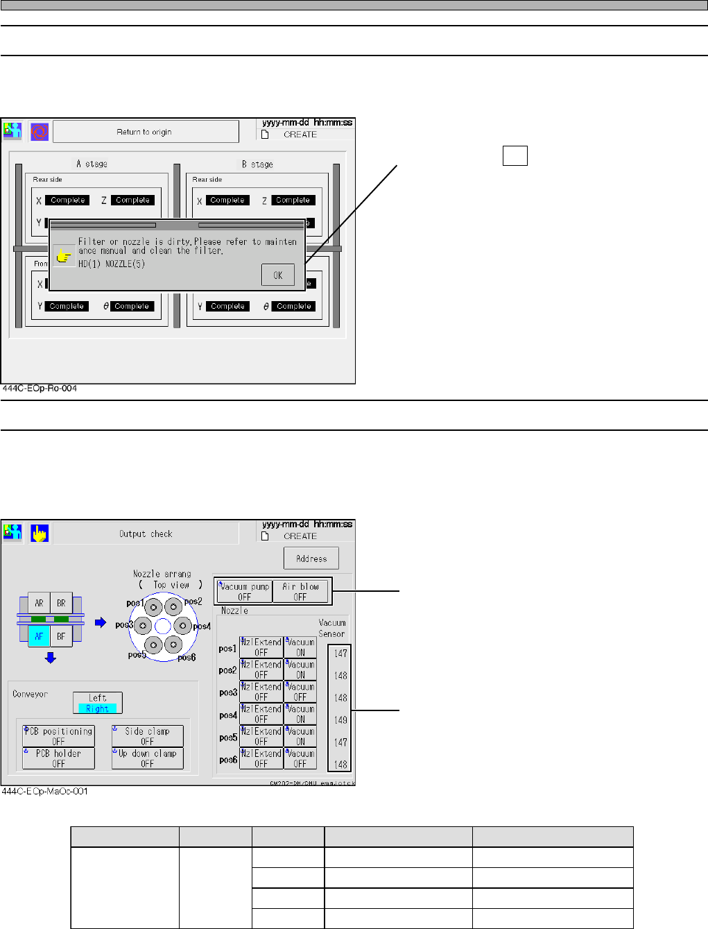
3-6-7 Nozzle Clogging Error
If the clogging of nozzle or the like is detected upon automatic operation, the message appears
and the operation aborts.
• In this case, the chip may be adhered to the
nozzle. Press OK to return to the main menu.
• Turn OFF the servo switch.
Check and clean the tip of the nozzle.
Turn ON the servo swith.
• Refer to the vacuum-sensor values at the
output check screen under the machine
adjustment screen.
3-6-8 Machine Adjustment Screen
When “Vacuum Sensor check” in the option configuration is set to ON, the vacuum-sensor values
are displayed on the output check screen under the machine adjustment screen.
The vacuum-pump-ON state and the air-blow-
ON state can be converted into numbers.
∗ Please note that the sensor values are subject to change without notice for improvements be
cause these are reference values.
sutatspmuP sutatsevlaV .oNelzzoN )ecnerefeR(eulavrosneS )ecnerefeR(gniggolcelzzoN
NOpmupmuucaVNOmuucaV
502002otesolC571
011512otesolC002
511522otesolC002
eromro021032otesolC002
Sensor values
Reference sensor values