444CEOM1-CM202.pdf - 第106页
Page 3-8 444C-E-OMA03-A01-01 Production Settings 3-2-4 Board T ransport This is used to perform transporting board in, transferring it from the stage A to B and transporting it out to the next process for each step. • Th…
Page 3-7
FUNCTIONS
3
444C-E-OMA03-A01-02
Production Settings
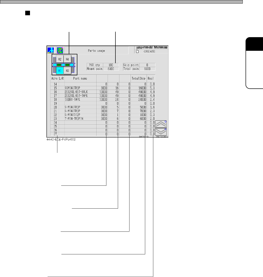
Result of calculation
Stage selection Board count
[Adrs] [L/R]
The address No. of feeder table
L/R shows left/right of double
feeder table.
Chip/Count
The number of the chips loaded
per reel
Mounting/Board
The number of the chips to be
mounted per board
Skip/Board
The number of the mounting skip
points per board
[Total Chip]
The consumption of chips to the
count of boards
[Reel]
The number of tape reels required
for the count of boards
Chip/Count
Mounting/
Board
Skip/Board
Page 3-8
444C-E-OMA03-A01-01
Production Settings
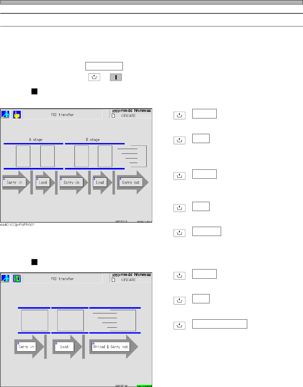
3-2-4 Board Transport
This is used to perform transporting board in, transferring it from the stage A to B and transporting
it out to the next process for each step.
• The board on the conveyor is displayed as a green rectangle. While it is being transported, its
image is blinking.
∗ After pressing PCB transfer on the production settings menu, make sure the servo switch is ON,
and then press
UNLOCK
→
START
.
CM202
[Stage A]
UNLOCK
+ Carry in
Transports the board in from the previous
process to the left conveyor on the stage A.
UNLOCK
+ Load
Transports the board from the left conveyor to
the right conveyor on the stage A.
[Stage B]
UNLOCK
+ Carry in
Transports the board from the right conveyor
on the stage A to the left conveyor on the stage
B.
UNLOCK
+ Load
Transports the board from the left conveyor to
the right conveyor on the stage B.
UNLOCK
+ Carry out
Transports the board from the right conveyor
on the stage B out to the next process.
CM201
UNLOCK
+ Carry in
Transports the board in from the previous
process to the left conveyor.
UNLOCK
+ Load
Transports the board from the left conveyor to
the right conveyor.
UNLOCK
+ Unload & Carry out
Transports the board from the right conveyor
out to the next process.
444C-EOp-PcPt-002
Page 3-9
FUNCTIONS
3
444C-E-OMA03-A01-05
Production Settings
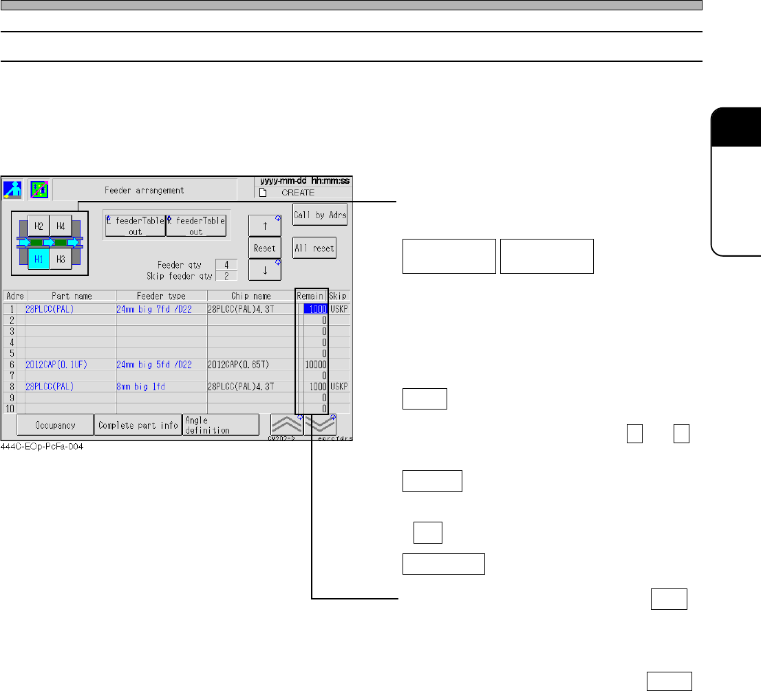
3-2-5 Feeder Arrangement
You can check which chip is on which feeder address.
First, check the state of the feeders arranged on the stage.
• The information of the chips on each feeder is displayed in the order of feeder address. Through
the state of occupancy, you can see which feeder address on the feeder table is used at a glance.
The number of the residual chips on each reel is also displayed.
• Select the feeder table you will check.
(CM201 has only the stage A.)
Draws out the selected feeder table. Pressing
the switch again returns the feeder table where
it was.
Reset
Resets the number of the residual chips
pointed by a cursor now. (Pressing ↑ and ↓
moves a cursor up and down.)
All reset
Resets the number of the residual chips on all
the feeders. When the message appears, press
Yes .
Call by Adrs
Pressing this switch displays the input screen.
When you enter an address and press ENT ,
a cursor moves to the specified address.
∗ When the remaining chip count is “0”, a yellow
mark lights up in this field. Check the feeder
and replace the workpieces. Pressing Reset
will reset the remaining count and delete the
yellow lit.
L feeder Table
out
R feeder Table
out
∗ For CM201-DS or CM202-DS, the feeder table
draw-out function is an option.