00194474-0702_AI_HeadReconfig_X_605_DE+EN.pdf - 第141页
Head Reconfiguration Kits 2 Assembly Instructions - SIPLACE X-Series Head Reconfiguration Kits 07/2010 Edition 141 2 Assembly Instructions - SIPLACE X-Series Head Reconfiguration Kit s 2.1 Head modularity The SIPLACE X o…
1 Montageanleitung Head Reconfiguration Kits SIPLACE X-Serie Head Reconfiguration Kits
Ausgabe 07/2010
140
1
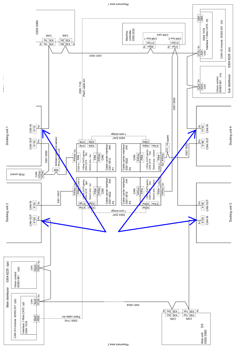
Abb. 1.15.9 Stromlaufplan 90010131-020301ld3 (Seite 3)
For Machines Serial No. >= B326
For IC-Camera (Type 33) 55x45 dig (Item.No. 03016339) >= FS 04
respectively
FC-Camera (Type 25) 16x16 dig (Item.No. 03020578-) >= FS03
Additional CAN Cable to conect to
IC-Camera (03050239- ) CAN-Bus: IC-Camera
FC-Camera (03050550-) CAN-Bus: IC- und FC-Camera

Head Reconfiguration Kits 2 Assembly Instructions - SIPLACE X-Series Head Reconfiguration Kits
07/2010 Edition
141
2 Assembly Instructions - SIPLACE
X-Series Head
Reconfiguration Kits
2.1 Head modularity
The SIPLACE X offers the following head configuration options: 2
2.1.1 X2 head modularity
X2
Placement area 1 Placement area 2 Can be figured from
SW version
603, SP1 only
Gantry 1 Gantry 3
Placement head
C&P20 C&P20
C&P20 C&P12
C&P20 C&P6
C&P20 TH
C&P12 C&P12
C&P12 C&P6
C&P12 TH
C&P6 C&P6
C&P6 TH
TH TH

2 Assembly Instructions - SIPLACE X-Series Head Reconfiguration Kits Head Reconfiguration Kits
07/2010 Edition
142
2.1.2 X3 head modularity
*Further information can be found in Chapter 2.1.4 ”Requirements and restrictions for the TwinHead in the 2-gantry area”2
X3
Placement area 1 Placement area 2 Can be configured
from SW version
603, SP1 only*
Gantry 1 Gantry 4 Gantry 3
Placement head
C&P20 C&P20 C&P20
C&P20 C&P20 C&P12
C&P20 C&P20 C&P6
C&P20 C&P20 TH
C&P12 C&P12 C&P12
C&P12 C&P12 C&P6
C&P12 C&P12 TH
C&P12 C&P6 C&P6
C&P12 C&P6 TH
C&P12 TH TH X
C&P6 C&P6 C&P6
C&P6 C&P6 TH
C&P6 TH TH X
TH TH TH X