00194474-0702_AI_HeadReconfig_X_605_DE+EN.pdf - 第208页
2 Assembly Instructions - SIPLACE X-Series Head Reconfiguration Kits Head Reconfiguration Kits 07/2010 Edition 208 : Check whether the CAN bus connector and th e ri bbon cable for the camera connection are plugged in. CA…
Head Reconfiguration Kits 2 Assembly Instructions - SIPLACE X-Series Head Reconfiguration Kits
07/2010 Edition
207
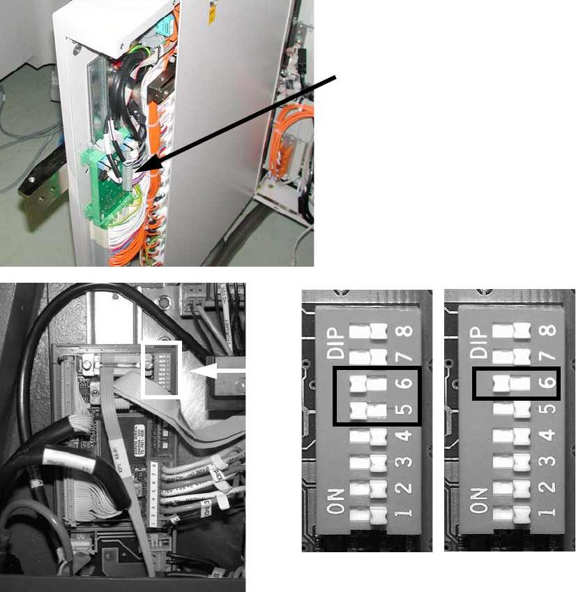
: Attach the CAN bus to X2.
: Attach the black camera cable to the VISION control unit.
: Changeover the DIP switch on the "Control unit 1 Vision stationary" (item no. 00363961-) :
– for a sub-distributor (SD): 5 and 6 to ON, the others to OFF.
– for a main distributor (MD): 6 to ON, the others to OFF.
2
See picture below or Chapter 2.15 ”Circuit diagrams” for machines up to serial number B325 (ig-
nore comments) 2
2
2
Control cable
for the vision control unit
SUB 2
MAIN 2
2 Assembly Instructions - SIPLACE X-Series Head Reconfiguration Kits Head Reconfiguration Kits
07/2010 Edition
208
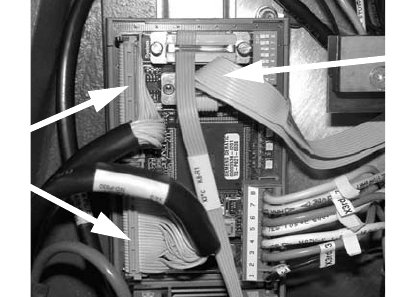
: Check whether the CAN bus connector and the ribbon cable for the camera connection are
plugged in.
CAN bus connector
Camera cable
Head Reconfiguration Kits 2 Assembly Instructions - SIPLACE X-Series Head Reconfiguration Kits
07/2010 Edition
209
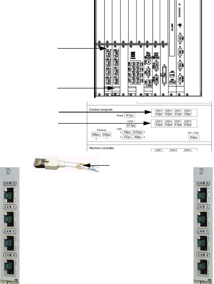
2.12.5 Hotlink card connections (computer unit)
Hotlink card for
cameras in PA 1
Hotlink card for
cameras in PA 2
Hotlink cable labeling
IC / FC camera in PA 1
X3pr
PCB/CO cameras in PA 1
Gantry 1, X0pr
PCB/CO cameras in PA 1
Gantry 4, X1pr
IC camera in PA 1
X2pr
IC / FC camera in PA 2
X3ps
IC camera in PA 2
X2ps
PCB/CO cameras in PA 2
Gantry 3, X1ps
PCB/CO cameras in PA 2
Gantry 2, X1ps
Hotlink card for
cameras in PA 1
Hotlink card for
cameras in PA 2