00194474-0702_AI_HeadReconfig_X_605_DE+EN.pdf - 第184页
2 Assembly Instructions - SIPLACE X-Series Head Reconfiguration Kits Head Reconfiguration Kits 07/2010 Edition 184 : Fit the strain relief using the three sc r ews on the lef t (see photograph above ). 2 2 2 The two righ…
Head Reconfiguration Kits 2 Assembly Instructions - SIPLACE X-Series Head Reconfiguration Kits
07/2010 Edition
183
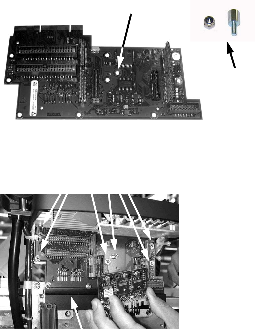
: Plug the DLM2 head adapter board (item no. 03019066-) from below into the head interface
board, and screw in place.
: Screw the bolts and nuts onto the adapter board before you fit it.
2
: Fit the SM board, modular (item no. 00344488-) on the DLM2 head adapter (using distance
bolts) and fix it with the corresponding screws.
Bolts
Spacer bolt, type B i/a-M3x7-ST Item no. 00324407-
Nut
DIN985 M3 - A2-70 Item no. 00328897-
Screws
DIN912 M3x6 - A2 Item no. 00201463-
Bolt with nut
Attach bolt here
Strain relief
2 Assembly Instructions - SIPLACE X-Series Head Reconfiguration Kits Head Reconfiguration Kits
07/2010 Edition
184
: Fit the strain relief using the three screws on the left (see photograph above).
2
2
2
The two right-hand screws must be removed - they are not needed. 2
2
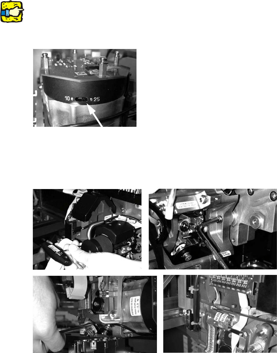
: Set the star resolution switch to 25.
The switch can be found underneath the placement head.
2
: Fit the placement head and fix in place with four screws.
Make sure that you use screws of the right length and observe the correct torque:
DIN912 M4x18 - 8.8 (item no. 00095023-), tightening torque: 2.7 Nm.
With screws two and three, you should first remove one sleeve to make the screws more ac-
cessible.
Head Reconfiguration Kits 2 Assembly Instructions - SIPLACE X-Series Head Reconfiguration Kits
07/2010 Edition
185
: Fit the component camera for the DLM head ( 4 screws DIN912 M4x10 - A2, item no.
00313069-).
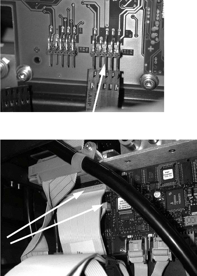
: Plug in the connectors for the DP axis.
2
: Plug in the two connectors.
2
: Clip on the strain relief pushbutton.