00194474-0702_AI_HeadReconfig_X_605_DE+EN.pdf - 第267页
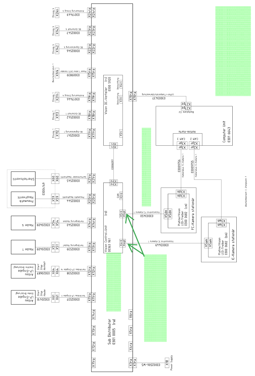
Head Reconfiguration Kits 2 Assemb ly Instructions - SIPLACE X-Series Head Reconfiguration Kits 07/2010 Edition 267 2 Fig. 2.15 - 3 90010131-010501ld3 circuit diagram (sheet 3) For Machines series No. <= B325 For IC-C…
2 Assembly Instructions - SIPLACE X-Series Head Reconfiguration Kits Head Reconfiguration Kits
07/2010 Edition
266
2
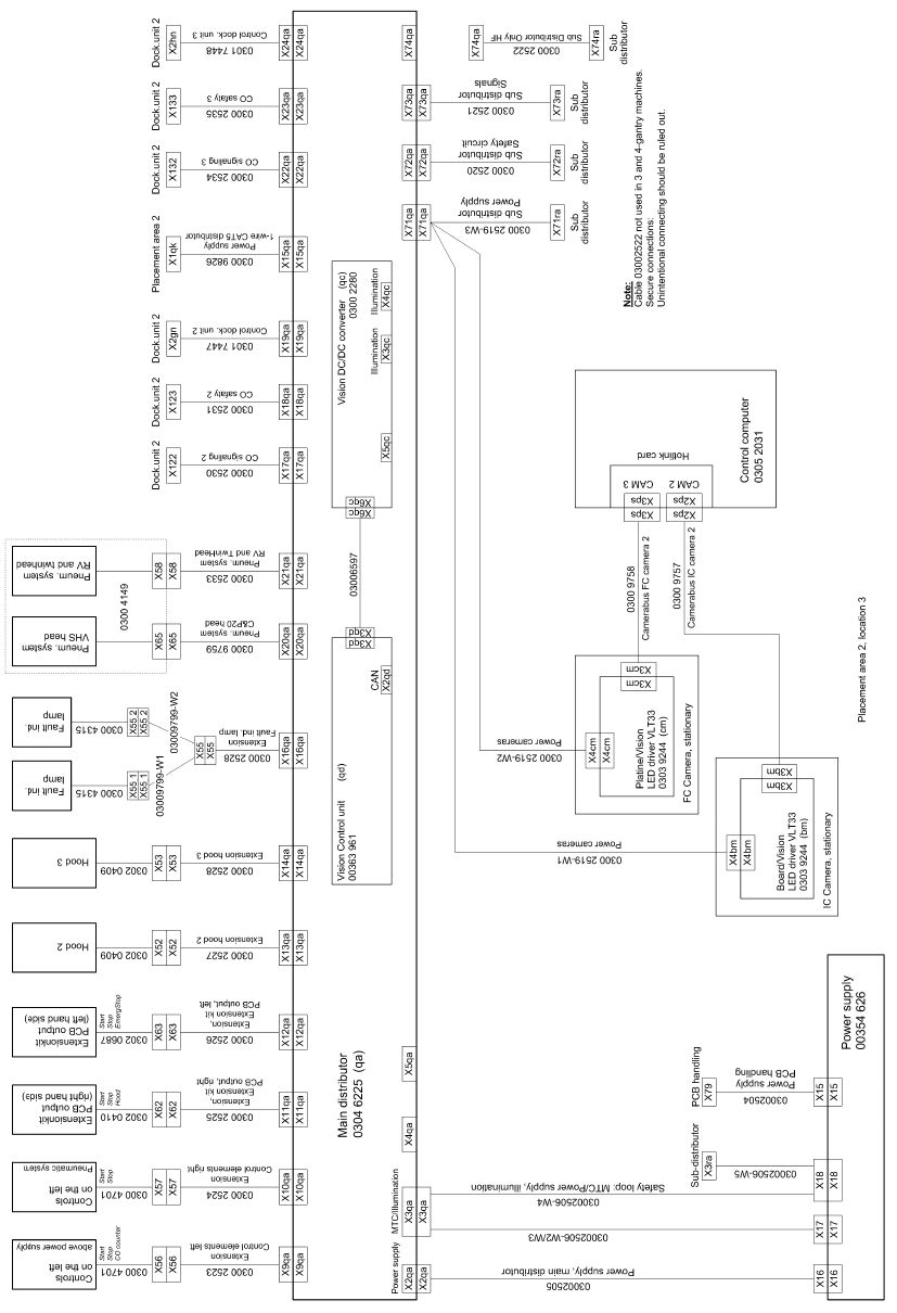
Fig. 2.15 - 2 90010131-010501ld3 circuit diagram (sheet 2)
For Machines series No.
B325
For IC-Camera (Type 33) 55x45 dig (Item.No. 03016339) < FS 04
respectively
FC-Camera (Type 25) 16x16 dig (Item.No. 03020578-) < FS03
no CAN Bus conected
no TQM Modul conected
IC-Camera 2 (placementarea 2, location 2)
Changes represent the wiering of
IC camera (Typ 33) 55x45 dig
(Item.No. 03016339)
FS04
respectively
FC-camera (Typ25) 16x16 dig
(Item.No. 03020578-)
FS 03
Please conect the "Adaptercabel Power Cameras"
(Item.No.03059912-01) between the "Controll-Unit 1
Vision stationär" and the black cable.
X4 - 03003449- eg. X5 - 03003450-
Head Reconfiguration Kits 2 Assembly Instructions - SIPLACE X-Series Head Reconfiguration Kits
07/2010 Edition
267
2
Fig. 2.15 - 3 90010131-010501ld3 circuit diagram (sheet 3)
For Machines series No. <= B325
For IC-Camera (Type 33) 55x45 dig (Item.No. 03016339) < FS 04
respectively
FC-Camera (Type 25) 16x16 dig (Item.No. 03020578-) < FS03
Changes represent the wiering of
IC camera (Typ 33) 55x45 dig
(Item.No. 03016339) >= FS04
respectively
FC-camera (Typ25) 16x16 dig
(Item.No. 03020578-) >= FS 03
Additional CAN cable for
IC-camera (03050239- ) CAN-Bus: IC-camera
FC-camera (03050550-) CAN-Bus: IC- and FC-camera
2 Assembly Instructions - SIPLACE X-Series Head Reconfiguration Kits Head Reconfiguration Kits
07/2010 Edition
268
2
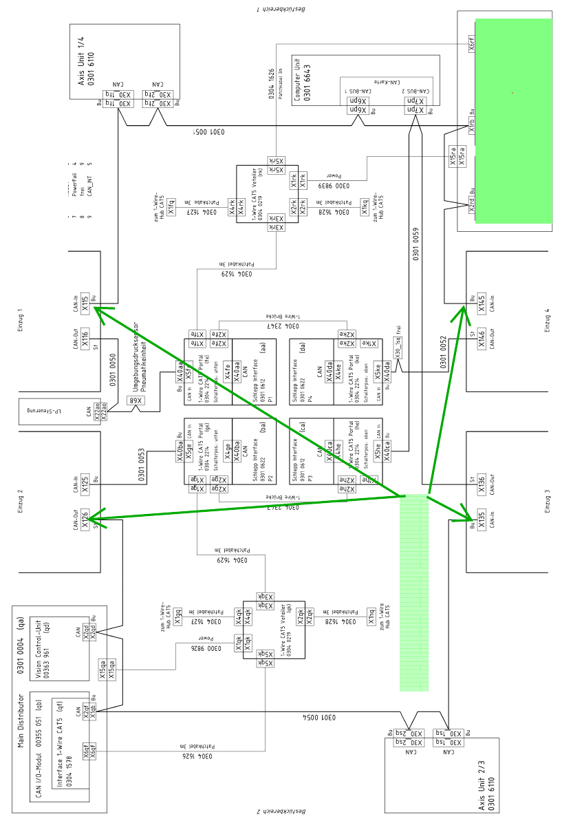
Fig. 2.15 - 4 90010131-020201ld3 circuit diagram (sheet 1)
For Machines with serieal No. >= B326
For IC-Camera (Type 33) 55x45 dig (Item.No. 03016339) >= FS 04
respectively
FC-Camera (Type25) 16x16 dig (Item.No. 03020578-) >= FS03
IC-Camera 2 (placementarea 2, location 2)