00194474-0702_AI_HeadReconfig_X_605_DE+EN.pdf - 第229页
Head Reconfiguration Kits 2 Assemb ly Instructions - SIPLACE X-Series Head Reconfiguration Kits 07/2010 Edition 229 : Fit the nozzle sta tion (item no.: 03045404-) using two screws "DIN7991 M4x2 0 - 8.8" (item …
2 Assembly Instructions - SIPLACE X-Series Head Reconfiguration Kits Head Reconfiguration Kits
07/2010 Edition
228
: Use the screws "DIN912 M3x18 -A2-70“ (item no.:03045034-) to attach the "Fine flow restrictor
GRO-QS-4-LF“ (item no.:03045754-) to the "Retaining plate for flow restrictor“ (item
no.:03046270-) and then use the screws "DIN7981 ST3.5x6.5-C-H-A2“ (item no.:03046777-)
to attach the plate to the tape guide channel (see photograph).
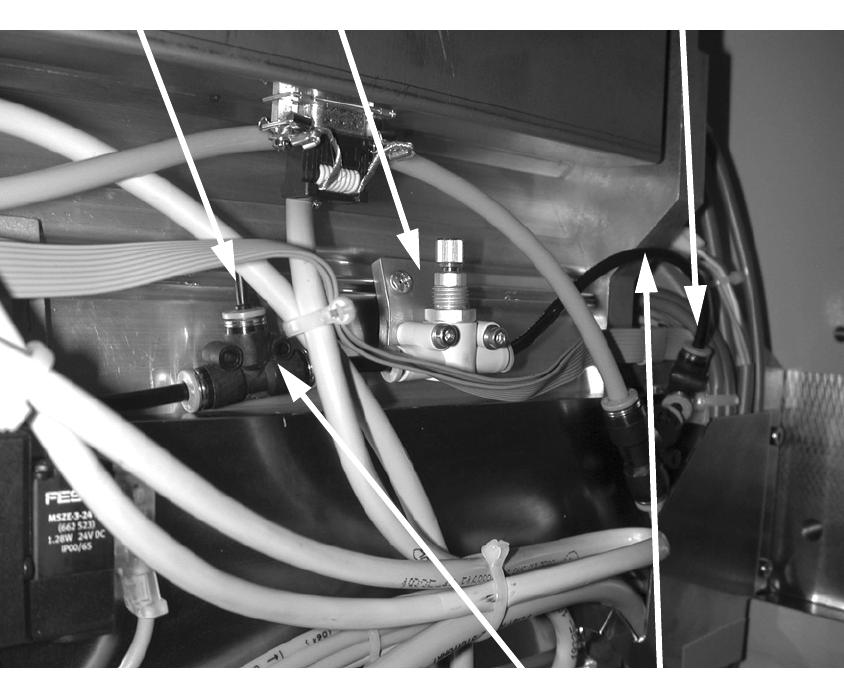
: Remove the "Plug QSC-4H" (item no.: 00330249-) for setting the forced air (see photograph).
: Connect the flow control valve to the "PUN-CM 4x0.75 70 mm" hoses (item no.: 03046291-)
using the two T-pieces.
2
2
2
2
2
2
T-piece for plug-in connector QSMT-4
Fine flow restrictor
Blanking plug
Connect flow control valve
using hoses
Head Reconfiguration Kits 2 Assembly Instructions - SIPLACE X-Series Head Reconfiguration Kits
07/2010 Edition
229
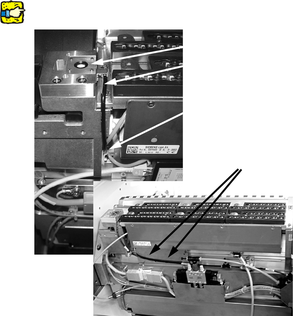
: Fit the nozzle station (item no.: 03045404-) using two screws "DIN7991 M4x20 - 8.8" (item no.:
00333782-).
: Run the long hose "PUN-CM 4x0.75 420 mm" (item no.: 03046432-) as far as the T-piece (see
photograph).
: Secure this hose with a cable clip "Clip Panduit CC S12-S08 D3.1 b 8.2" (item no.
00368063-) and a screw "DIN912 M3x6 - A2-70" (item no.:03045028-).
2
Make sure that the hose is run in front of the retaining plate for the 1-wire hub. 2
2
Nozzle station
Hose "PUN-CM 4x0.75 420 mm"
Cable clip
Hose run
2 Assembly Instructions - SIPLACE X-Series Head Reconfiguration Kits Head Reconfiguration Kits
07/2010 Edition
230
Compressed air setting 2
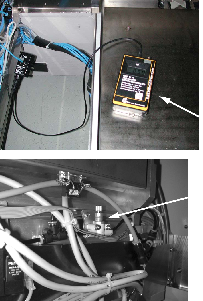
: Connect a forced air measuring device to the T-piece (plug).
Use the fine flow restrictor to set a pressure of 0.5 bar.
2
2
2
Fine flow
restrictor
Measuring
device: