00194474-0702_AI_HeadReconfig_X_605_DE+EN.pdf - 第169页
Head Reconfiguration Kits 2 Assemb ly Instructions - SIPLACE X-Series Head Reconfiguration Kits 07/2010 Edition 169 : Loosen the four screws on each T winHead module and remove both mod ules. 2 : Loosen the six screws on…
2 Assembly Instructions - SIPLACE X-Series Head Reconfiguration Kits Head Reconfiguration Kits
07/2010 Edition
168
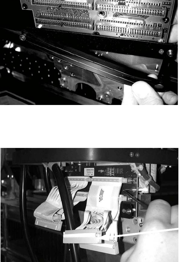
: Open the strain relief clip (pushbutton).
2
: Unscrew the entire strain relief.
: Detach the four ribbon cables from the TwinHead (photograph below).
2
Plug
Head Reconfiguration Kits 2 Assembly Instructions - SIPLACE X-Series Head Reconfiguration Kits
07/2010 Edition
169
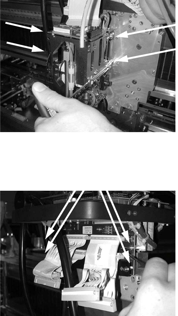
: Loosen the four screws on each TwinHead module and remove both modules.
2
: Loosen the six screws on the head interface board and remove the board.
Be careful not to lose the washers!
2
2
2
Screws
2 Assembly Instructions - SIPLACE X-Series Head Reconfiguration Kits Head Reconfiguration Kits
07/2010 Edition
170
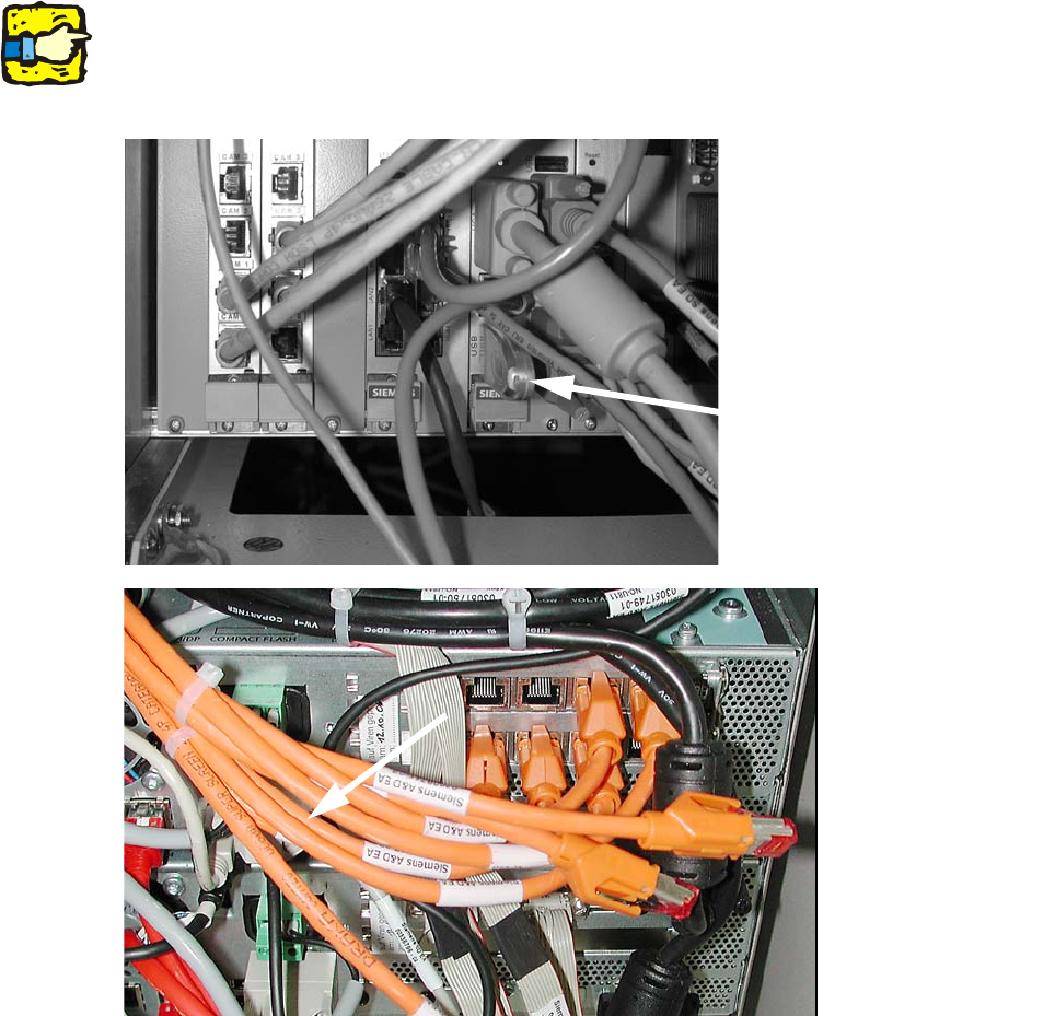
2.10 Removing the C&P 20 placement head
2
The C&P 20 placement head must be fitted on both gantries on placement areas with two gantries.
It cannot be used together with other placement heads in a placement area. 2
: Plug a USB stick or another suitable storage medium into the USB slot on the station computer.
2
2
: Save the machine data to the storage medium.
: Undock the component trolleys.
: Switch the placement machine off at the main power switch.
USB stick
(computer unit)
USB stick
(box PC)