00194474-0702_AI_HeadReconfig_X_605_DE+EN.pdf - 第152页
2 Assembly Instructions - SIPLACE X-Series Head Reconfiguration Kits Head Reconfiguration Kits 07/2010 Edition 152 2.5 Placement head replacement sequence

Head Reconfiguration Kits 2 Assembly Instructions - SIPLACE X-Series Head Reconfiguration Kits
07/2010 Edition
151
2.4 Safety instructions
WARNING
The safety instructions from the “Operational safety” chapter of the user manual and servicing in-
structions take precedence over these instructions. 2
SIPLACE placement machines are supplied with main power voltage.
Consequently parts of these systems carry dangerous voltages! This voltage is present at certain
modules inside the machine base, even when the machine is switched off at the main power
switch.
Incorrect handling of the placement machine or touching live parts of the machine can result in
death or severe injury, and considerable damage to equipment.
BEFORE starting any work, shut down the operating system correctly, then switch the machine
OFF at the main power switch and disconnect from the main power supply. In addition, the com-
pressed air supply must be switched off at the compressed air unit's main valve in the machine
base and vented by actuating the needle valve on the compressed air unit.
There is DANGER for heart pacemaker wearers in the vicinity of the linear motors, as described
in detail in the "Special safety instructions for working in the vicinity of strong magnetic fields"
section of the user manual and service manual.
Always follow the accident prevention regulations, DIN or other standards and special safety
rules applicable in your country.
Pay attention to the information concerning residual voltages in the Operational Safety chapter.
Follow the ESD regulations as described in the operational safety section of the operating
instructions.
During the retrofit, always secure the machine to prevent access by other people and to prevent
it being switched on again. The procedure is described in the “Locking the machine…” section of
the user manual.
Working with the SITEST program further increases the risk of accident.
The SITEST program must only be used by authorized and trained personnel.
2
2.4.1 Definitions
2
Please note 2
2
2
2
Caution 2
2 Assembly Instructions - SIPLACE X-Series Head Reconfiguration Kits Head Reconfiguration Kits
07/2010 Edition
152
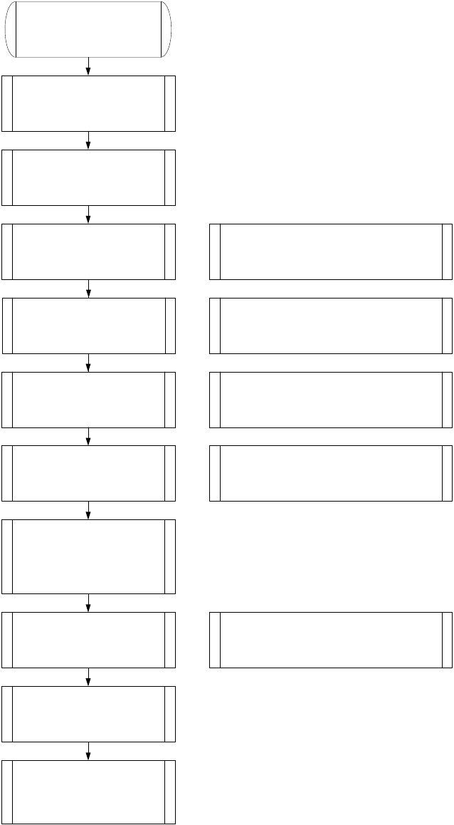
2.5 Placement head replacement sequence
Head Reconfiguration Kits 2 Assembly Instructions - SIPLACE X-Series Head Reconfiguration Kits
07/2010 Edition
153
2
1. Make a backup for the exist
machine configuration.
2. Machine data - backup with the
Sitest and create a folder
e.g. Backup and store the folder
SRCMA.
4. Confirm the configuration,
machine will shutdown
automatically
Switch off the machine!
6. Mechanical works:
Mount the Head, adapterboard
and Nozzlechanger.
7. Switch ON the machine
Look to the error messages
Set the nozzle on the head and
check the nozzle changer.
Note: Save the zero point correction from the
EEPROM to the Achsver.ma.
Check the firmware!
8. Siplace Pro computer:
Make a copy of the exist basic set
up and configure into the copy the
new head type and
nozzlechanger
Note: As a result the new configuration will be
send to the station.
9. Siplace Pro computer:
Send a placement program, e.g.
with one component to the
station.
10. Station:
Check the axis dynamic and
calibrate all heads and cameras.
11. Station:
Start the production.
Note: Stop the current job from Siplace Pro
before you shutdown the machine.
5. Mechanical works:
Head, Nozzlechanger and
adapterboard exchange.
Note: Don`t change the adapterboard if you
change from C&P6 < -- > C&P12 head. Change
the Servo amplifier and don`t forget the DC/DC
converter for C&P 20 head.
Note: Preparations of the head plate (sealing with grub
screw, attention different length of the head screws)
Height adjustment nozzlechanger and different pressure
air supply for C&P20 head!
C&P20 X-Feeder Docking unit
3. SITEST: Machine configuration
(Head type, nozzle changer,
cameras).