00194474-0702_AI_HeadReconfig_X_605_DE+EN.pdf - 第189页
Head Reconfiguration Kits 2 Assemb ly Instructions - SIPLACE X-Series Head Reconfiguration Kits 07/2010 Edition 189 Gantries CFK 02 and CFK 04 Gantry CFK 06 Plug QSC-6H Item no . 00337891- Plug QSC-4H Item no . 00330249-…
2 Assembly Instructions - SIPLACE X-Series Head Reconfiguration Kits Head Reconfiguration Kits
07/2010 Edition
188
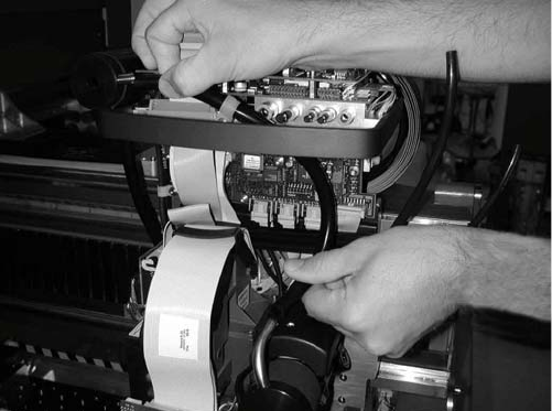
: Connect the top and bottom hoses.
2.11.3 Connections on the compressed air distributor
There are currently two different pneumatic distributors available depending on the cable and
hose carrier installed:
– Use the old cable and hose carrier on CFK gantries 02 and 04 for the old pneumatic distributor
and
– the new pneumatic distributor for the "CFK 06 gantry, new cable and hose carrier". These new
distributors are prepared for the vacuum pump on the C&P 20 head option.
Head Reconfiguration Kits 2 Assembly Instructions - SIPLACE X-Series Head Reconfiguration Kits
07/2010 Edition
189
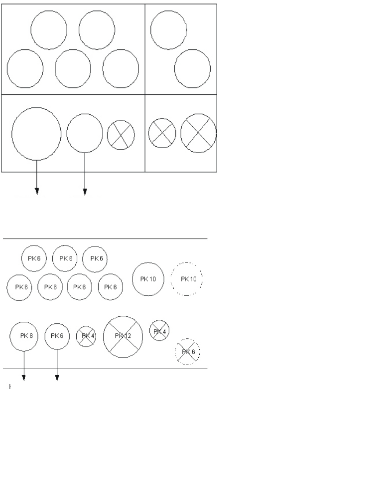
Gantries CFK 02 and CFK 04
Gantry CFK 06
Plug QSC-6H Item no. 00337891-
Plug QSC-4H Item no. 00330249-
Plug QSC-8H Item no. 03010908-
Plug QSC-10H Item no. 00324874-
Plug QSC-12H Item no. 03015210-
Up to machine serial
no. B-078
Holding circuit Pickup circuit
Pneumatic distributor back
Input:
7x pneumatic hose
Pneumatic distributor front
Output:
DLM head 6/12
Holding circuit Pickup circuit
Pneumatic distributor back
Input:
7x pneumatic hose (PK6)
2x pneumatic hose
vacuum pump option (PK10)
Pneumatic distributor front
Output:
DLM head 6/12
From machine serial
no. B-079
2 Assembly Instructions - SIPLACE X-Series Head Reconfiguration Kits Head Reconfiguration Kits
07/2010 Edition
190
2.11.4 Replacing the servo cards
2
Wear an ESD armband for the whole time you are working on the placement head and servos. 2
2
: Use the machine key to open the door of the servo unit.
2
Insert the axis and servo cards in accordance with your machine configuration.
Please note the overviews in the appendix Chapter 2.14.1 or Chapter 2.14.2.
2
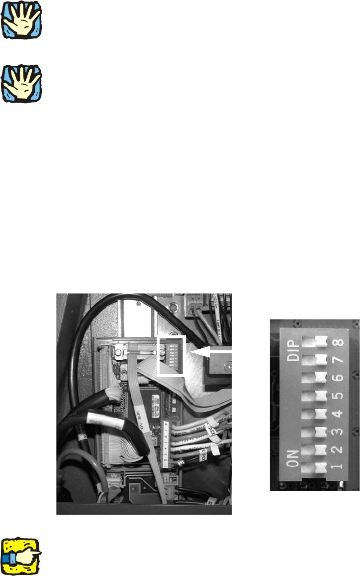
2.11.5 Setting the dip switches for the C&P 6/12 vision control unit
(up to machine serial no. B325)
: Set the dip switches on the vision control unit to OFF, if it is not a two-gantry area with Twin-
Head.
: The vision control unit for placement area 1 is located in the main distributor (location 4).
: The vision control unit for placement area 2 is located in the main distributor (location 2).
: Leave the configuration for the TwinHead as described in Chapter 2.12.4 "Setting the DIP
switches on the vision control unit for the TwinHead".
2
2
If there is no TwinHead installed in the same placement area, you can remove the corresponding
vision controller in the sub or main distributor. C&P heads do not require a vision controller. 2
OFF
OFF
OFF
OFF
OFF
OFF
OFF
OFF