00194474-0702_AI_HeadReconfig_X_605_DE+EN.pdf - 第239页
Head Reconfiguration Kits 2 Assemb ly Instructions - SIPLACE X-Series Head Reconfiguration Kits 07/2010 Edition 239 2 : If problems occur with the CAN bus, measu re the resist ance between pin 7 (CAN High) and pin 2 (CAN…
2 Assembly Instructions - SIPLACE X-Series Head Reconfiguration Kits Head Reconfiguration Kits
07/2010 Edition
238
2
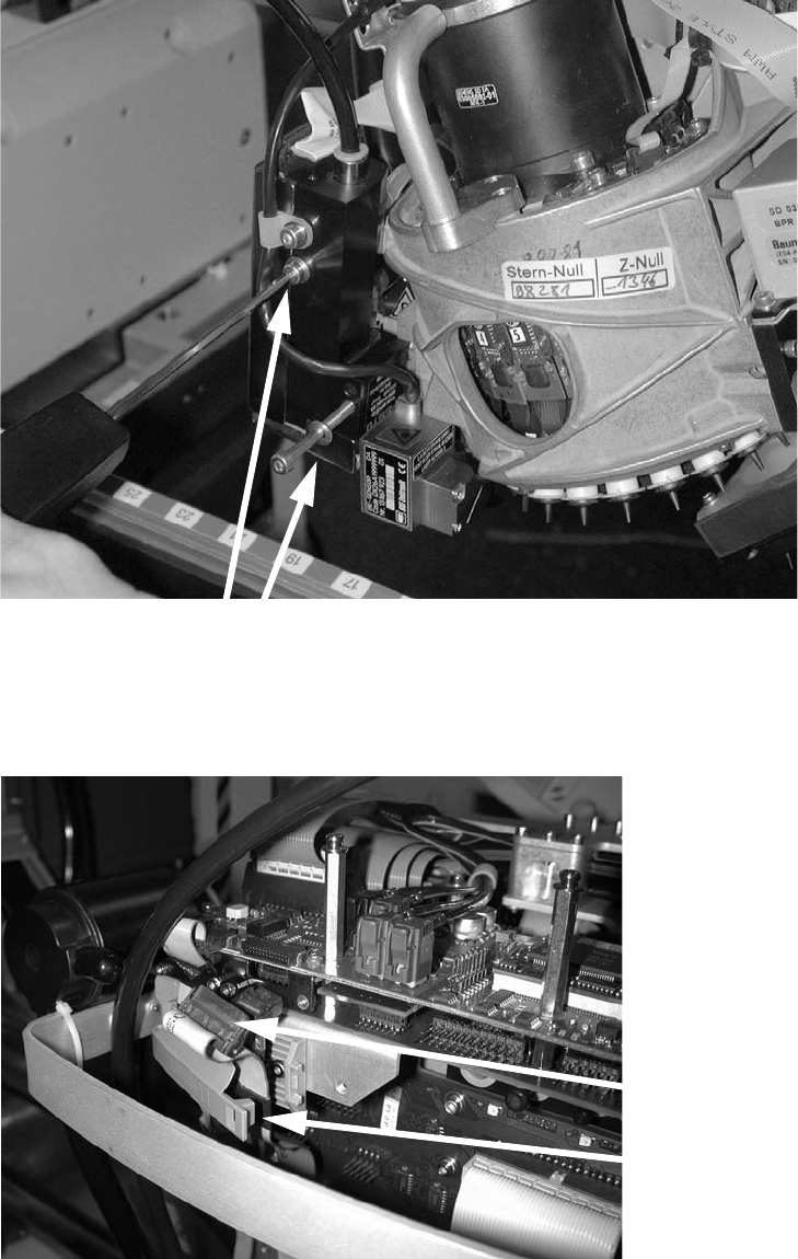
: Connect the plugs and attach the clip.
2
2
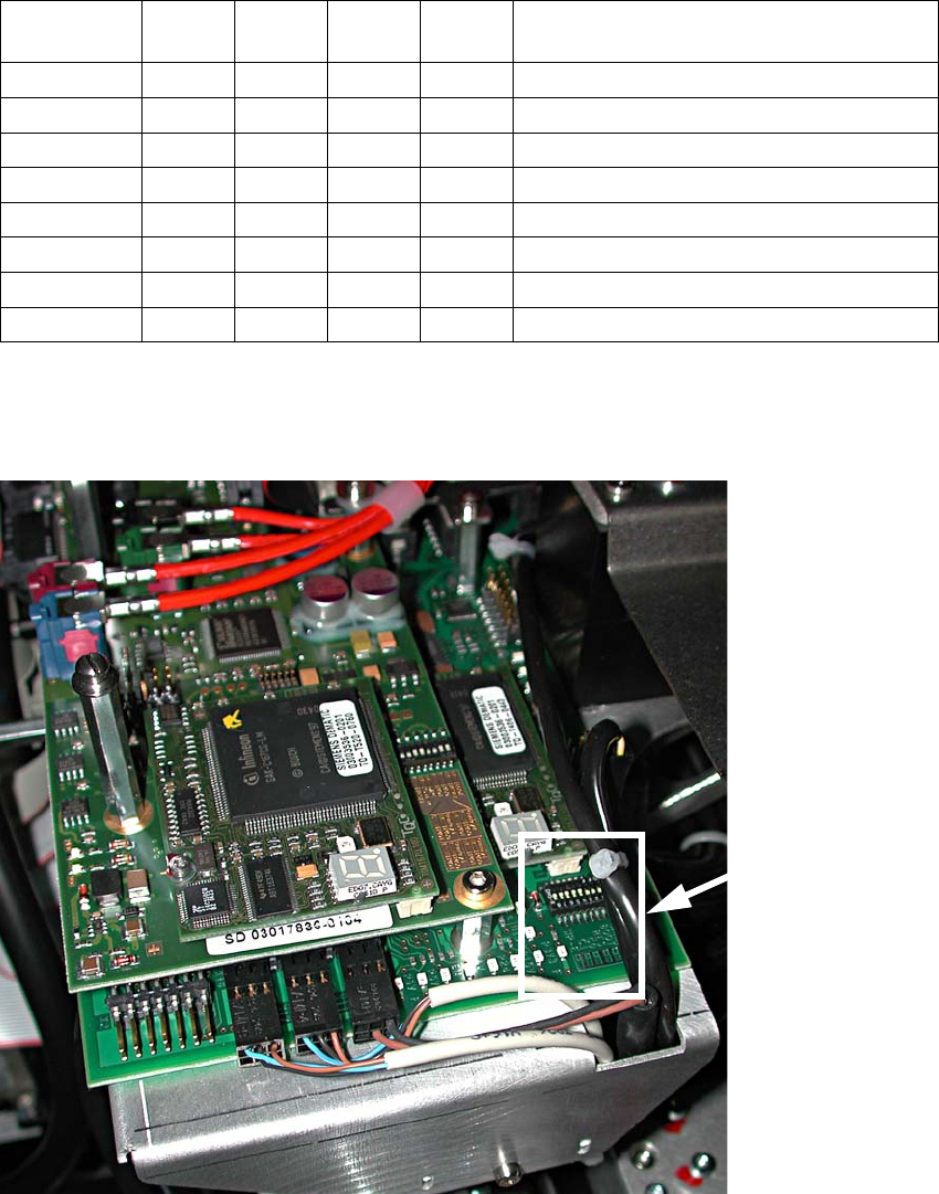
: Check the jumper settings on the C500 head interface board.
Tighten the screw
Attach the clip
Plug in the connec-
Head Reconfiguration Kits 2 Assembly Instructions - SIPLACE X-Series Head Reconfiguration Kits
07/2010 Edition
239
2
: If problems occur with the CAN bus, measure the resistance between pin 7 (CAN High) and
pin 2 (CAN Low). It should be 60 Ohm.
2
2
Jumper
Gantry
1
Gantry
2
Gantry
3
Gantry
4
1
0 1 0 1 Gantry ID0
2
0 0 1 1 Gantry ID1
3
1 1 1 1 120 Ohm CAN terminating resistor
4
0 0 0 0 Boot
5
0 0 0 0 Reset
6
0 0 0 0 CAN ID0
7
0 0 0 0 CAN ID1
8
0 0 0 0 Write protect deactivated
Jumper
position
2 Assembly Instructions - SIPLACE X-Series Head Reconfiguration Kits Head Reconfiguration Kits
07/2010 Edition
240
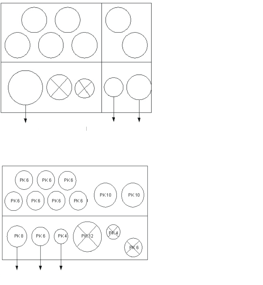
2.13.6 Connections on the compressed air distributor
There are currently two different pneumatic distributors available depending on the cable and
hose carrier installed:
– Use the old cable and hose carrier on CFK gantries 02 and 04 for the old pneumatic distributor
and
– the new pneumatic distributor for the "CFK 06 gantry, new cable and hose carrier". These new
distributors are prepared for the vacuum pump on the C&P 20 head option.
2
Gantries CFK 02 and CFK 04
Gantry CFK 06
Pneumatic distributor back
Input:
7x pneumatic hose (PK6)
2x pneumatic hose
vacuum pump option (PK10)
Pneumatic distributor front
Output:
C+P 20 head
Pneumatic distributor back
Input:
7x pneumatic hose
Pneumatic distributor front
Output:
C+P 20 head
Return cylinder
Pressure
control valve
Holding
circuit
Holding
circuit
Return
cylinder
Pressure
control valve