00194474-0702_AI_HeadReconfig_X_605_DE+EN.pdf - 第174页
2 Assembly Instructions - SIPLACE X-Series Head Reconfiguration Kits Head Reconfiguration Kits 07/2010 Edition 174 : Disconnect the air hose. Close the Y piece using a 00330249 plu g QSC-4H . 2 2 : Remove the nozzle stat…
Head Reconfiguration Kits 2 Assembly Instructions - SIPLACE X-Series Head Reconfiguration Kits
07/2010 Edition
173
2.10.3 Removing the nozzle station (description for the new component trolley
docking unit 03015680-07 with CAN node for tape cutter control board)
2
The component trolley docking unit must be released according to the installation location (single
portal placement area) and pushed outwards.
It is essential to read the respectively valid service manual in this connection.
Fasten the component trolley docking unit in place after completing the work and measure all at-
tachment parts (nozzle changer). 2
2
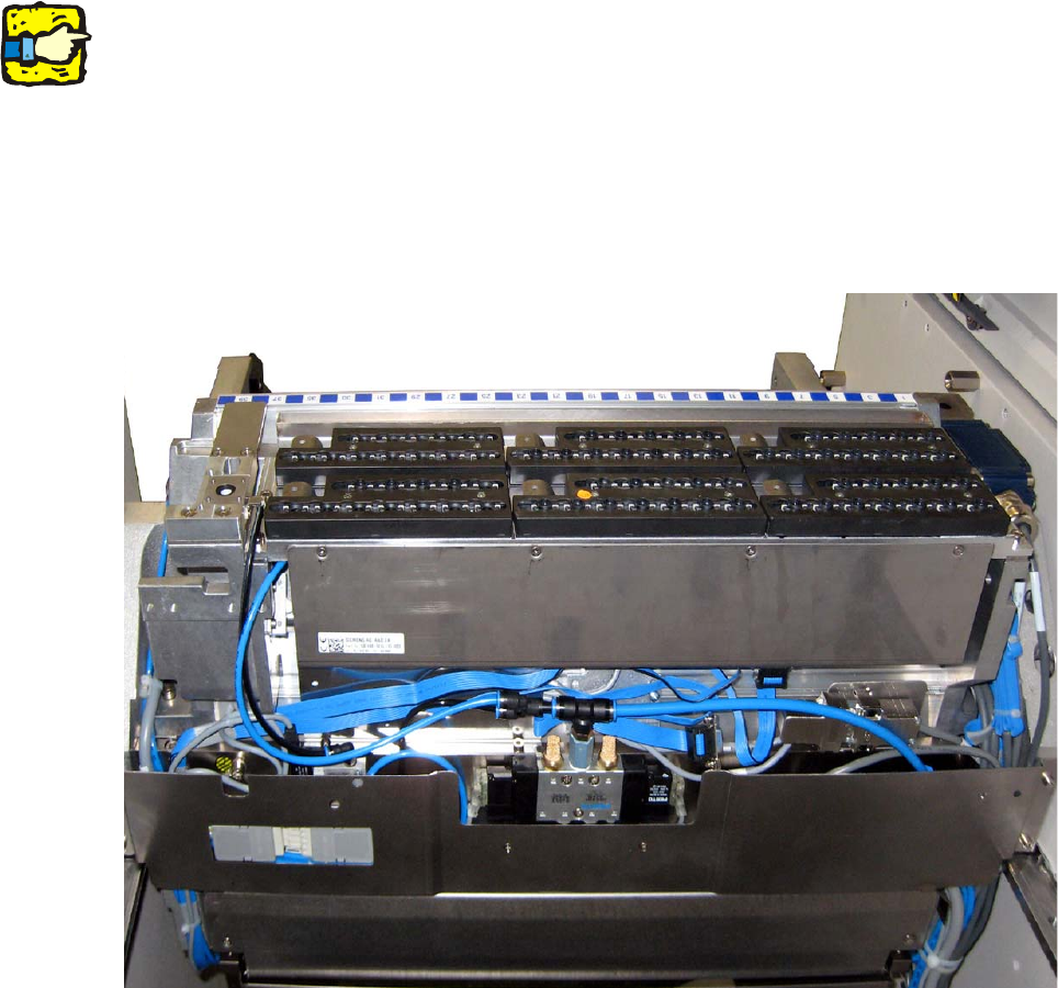
: Remove the cover plate from the component trolley docking unit.
2
2
2
2
2
2
2
2 Assembly Instructions - SIPLACE X-Series Head Reconfiguration Kits Head Reconfiguration Kits
07/2010 Edition
174
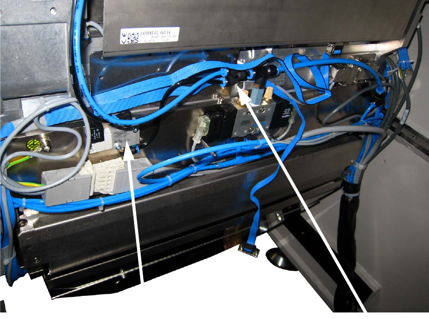
: Disconnect the air hose.
Close the Y piece using a 00330249 plug QSC-4H
.
2
2
: Remove the nozzle station valve completely.
2
2
2
2
2
2
2
2
2
Y adapter
Solenoid valve
Head Reconfiguration Kits 2 Assembly Instructions - SIPLACE X-Series Head Reconfiguration Kits
07/2010 Edition
175
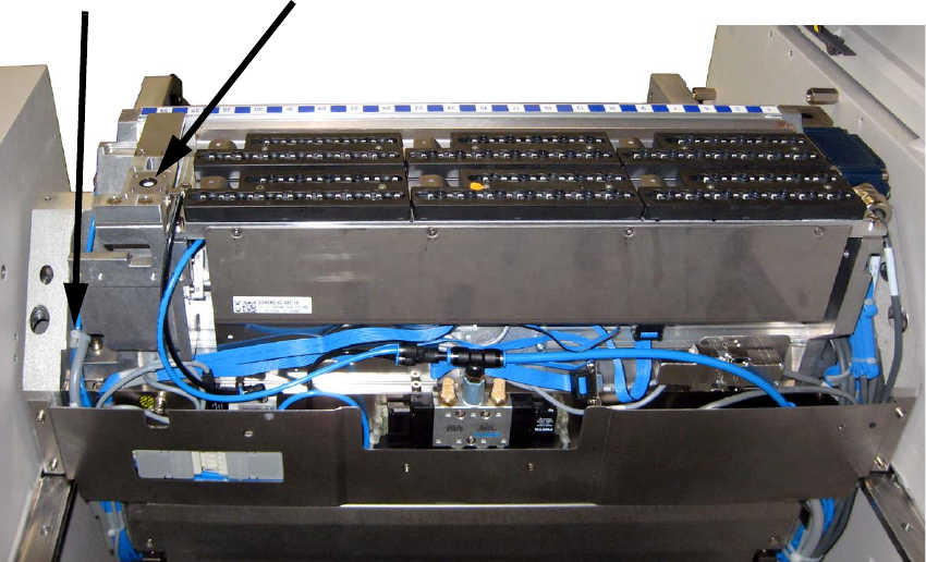
: Remove the nozzle station and the cable clip.
2
2
: Refit the cover on the component trolley docking unit.
2
2
2
2
2
2
2
2
2
2
2
2
Cable clip
Nozzle station