00194474-0702_AI_HeadReconfig_X_605_DE+EN.pdf - 第234页
2 Assembly Instructions - SIPLACE X-Series Head Reconfiguration Kits Head Reconfiguration Kits 07/2010 Edition 234 2.13.5 Inst alling the placement head 1.Preparation of the head plate 2 In order to facilitate the replac…
Head Reconfiguration Kits 2 Assembly Instructions - SIPLACE X-Series Head Reconfiguration Kits
07/2010 Edition
233
: Set the distance for all placement heads to 139.0 +/- ±0.2 mm.
If the distance is correct, continue by installing the nozzle changer in the placement machine.
2
: If the distance is too large, place adjusting plates beneath:
Adjusting plates for nozzle reject device (item no.: 03039514-),
screws DIN7991 M4x20 - 8.8 (item no.: 00333782-).
2
2
2
2
2
2
2
2
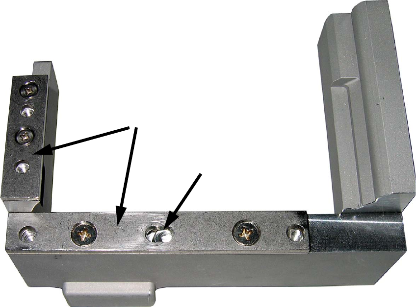
Slot
Adjusting plates
2 Assembly Instructions - SIPLACE X-Series Head Reconfiguration Kits Head Reconfiguration Kits
07/2010 Edition
234
2.13.5 Installing the placement head
1.Preparation of the head plate 2
In order to facilitate the replacement and mounting of heads, changes have been made to the
"C&P20A placement head / without camera" [03058420-03] and the "CPP placement head / with-
out camera" [03053528-xx] (Multistar). 2
A retrofitting kit is also offered to allow the retaining plate on C&P20A and CPP placement heads
also to be used on machines that are not yet fitted with the mounting aid. 2
03073841-01 "FHE retrofitting kit for X-Series" 2
The reconfiguration kit contains the retroffiting kit (03073841-01 "FHE retroffiting kit for X-Series").2
2
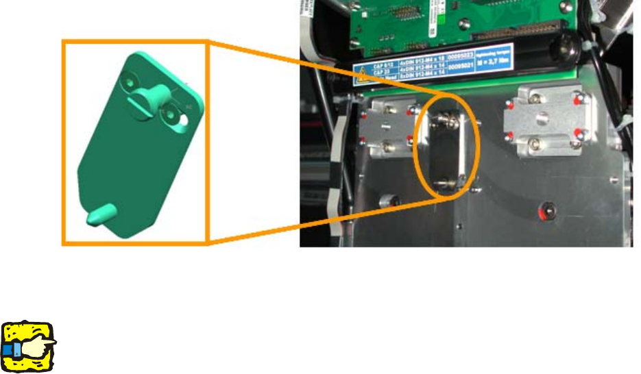
Fig. 2.13 - 1 Mounting position for the FHE mounting aid
: Attach the FHE mounting aid with the two screws
2
CAUTION:
A placement head that is only attached to the gantry using the FHE lug hangs around 3 mm lower
than a head that has been screwed on. You should therefore only attach the placement head in
positions where there is sufficient clearance underneath. 2
Do not move the gantry as long as the head is not secured! 2
2.Preparation of the head plate 2
: Place the DLM head template on the head fixing plate.
Remove any excess screws and add any necessary screws:
fixing screws: 4x DIN912 M4x14 - 8.8 (item no. 00095021-),
sealing screws: 9x DIN913 M4x6 - ST (item no. 00309422-), secure with gray thread lock paint
(item no. 00318199-)!
Screws in the wrong place could affect the flow of cooling air to the X-axis motor.
Head Reconfiguration Kits 2 Assembly Instructions - SIPLACE X-Series Head Reconfiguration Kits
07/2010 Edition
235
2
2
2
Always use the extension straight TX20 for Heads with FHE, because this heads have torx
screws!
Make sure that the screws are of the right length. The lengths are different for C&P heads and the
TwinHead. Tightening torque for the fixing screws: 2.7 Nm.
If you use the wrong screws, there is a risk of damaging the thread in the head plate. 2
2
: Screw on the head adapter board (item no.: 03002870-)
(6 screws DIN912 M3x6 - A2, item no.: 00201463-).