00194474-0702_AI_HeadReconfig_X_605_DE+EN.pdf - 第211页
Head Reconfiguration Kits 2 Assemb ly Instructions - SIPLACE X-Series Head Reconfiguration Kits 07/2010 Edition 211 : Insert the new reject bin. 2 : Insert the new nozzle changer (P&P / T winHead) and fix in place wi…
2 Assembly Instructions - SIPLACE X-Series Head Reconfiguration Kits Head Reconfiguration Kits
07/2010 Edition
210
2
More precise information on this can be found in the appendix in Chapter 2.15 ”Circuit diagrams”.
2
Hotlink cables that are not being used MUST NOT be plugged in.
Do not confuse the hotlink cable with twisted pair cables!!!
2
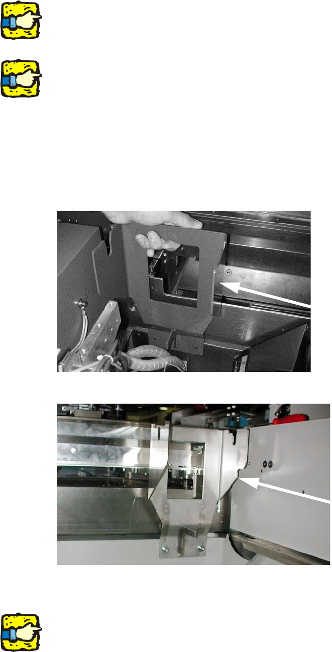
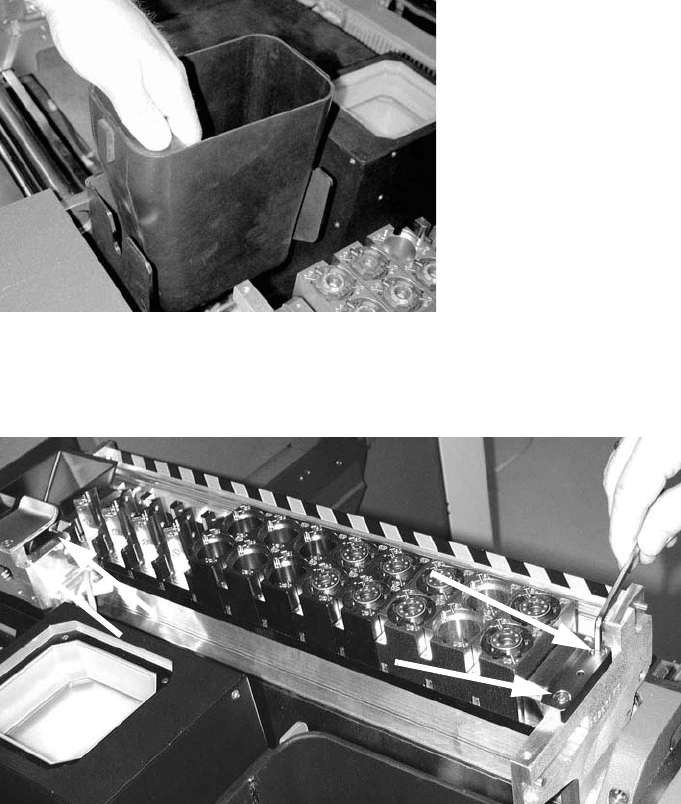
2.12.6 Converting the nozzle changer and the component reject bin
: Insert the fixing for the P&P / TwinHead reject bin and screw it on (fixing screws for holder for
the P&P reject bin DIN912 M6x14 - 8.8, item no.:
0095046-).
2
2
: Remove the sensor for the C&P head reject bin and wire it to the new reject bin for the P&P or
TwinHead.
2
On the subject of the reject bin sensor, also read the assembly instructions for the reject bin sen-
sor, SIPLACE HF series / X series (item no.:00194550-). 2
Locations 1 and 3
Locations 2 and 4
Head Reconfiguration Kits 2 Assembly Instructions - SIPLACE X-Series Head Reconfiguration Kits
07/2010 Edition
211
: Insert the new reject bin.
2
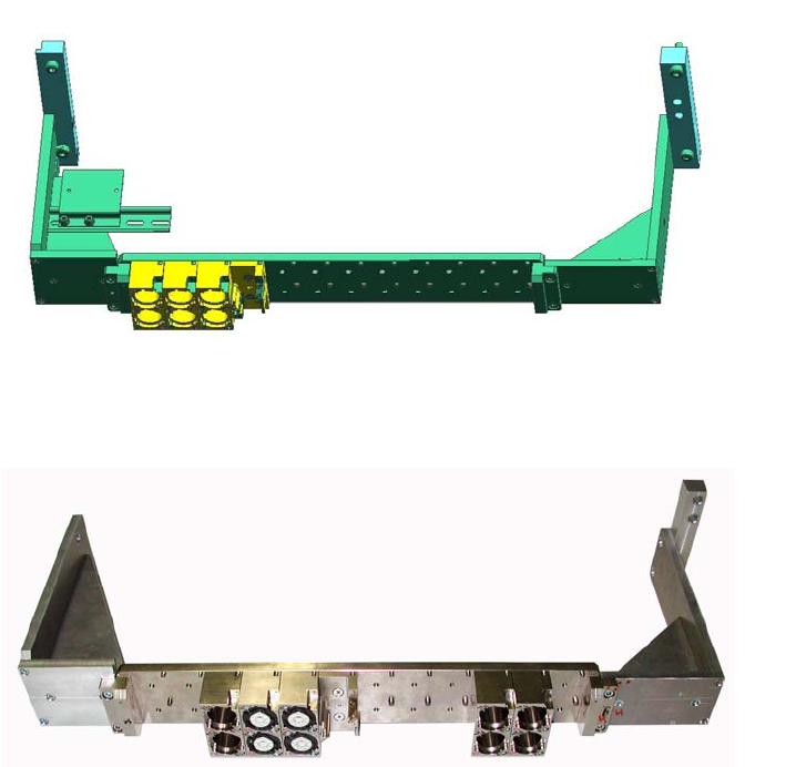
: Insert the new nozzle changer (P&P / TwinHead) and fix in place with four screws (screws for
the NC P&P TwinHead mount: DIN912 M5x14 - 8.8, item no.: 0306631-).
2
2
Installation nozzle changer on location with MTC 2
You need "nozzle changer TwinHead before the MTC X-series" (item no. 00119747-) at a location
with MTC. The holder of the nozzle changer for machine with the MA No. Bxxx(one part as
machine frame) Dxxx (two parts as machine frame) are different. This retrofit kit include the holder
for the nozzle changer Twin Head (Art.Nr. 03049891-02) for both machine frames. 2
A prerequisite is that a MTC docking unit frame (item no. 03009963-) is already installed with the
function status 03. Also observe the "Installation instructions MTC2 on the SI"
(item no. 00193897-01) 2
2
2 Assembly Instructions - SIPLACE X-Series Head Reconfiguration Kits Head Reconfiguration Kits
07/2010 Edition
212
: Attach the changer with 4 x DIN912 M5x14 - 8.8, (item no. 0306631-) on both holders.
2
Fig. 2.12 - 3 TH - Nozzlechanger for X-Machine with MTC and MA No. Dxxx
Fig. 2.12 - 4 TH - Nozzlechanger for X-Machine with MTC and MA No. Bxxx
: Attach the nozzle changer incl. holder on the machine frame or the supporting disc of the MTC
drawer frame (on the left with M6x30; on the right with M6x45).