00194474-0702_AI_HeadReconfig_X_605_DE+EN.pdf - 第170页
2 Assembly Instructions - SIPLACE X-Series Head Reconfiguration Kits Head Reconfiguration Kits 07/2010 Edition 170 2.10 Removing the C&P 20 placement head 2 The C&P 20 placement head m ust be fitted on both gantr…
Head Reconfiguration Kits 2 Assembly Instructions - SIPLACE X-Series Head Reconfiguration Kits
07/2010 Edition
169
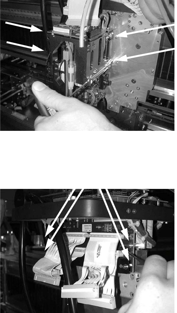
: Loosen the four screws on each TwinHead module and remove both modules.
2
: Loosen the six screws on the head interface board and remove the board.
Be careful not to lose the washers!
2
2
2
Screws
2 Assembly Instructions - SIPLACE X-Series Head Reconfiguration Kits Head Reconfiguration Kits
07/2010 Edition
170
2.10 Removing the C&P 20 placement head
2
The C&P 20 placement head must be fitted on both gantries on placement areas with two gantries.
It cannot be used together with other placement heads in a placement area. 2
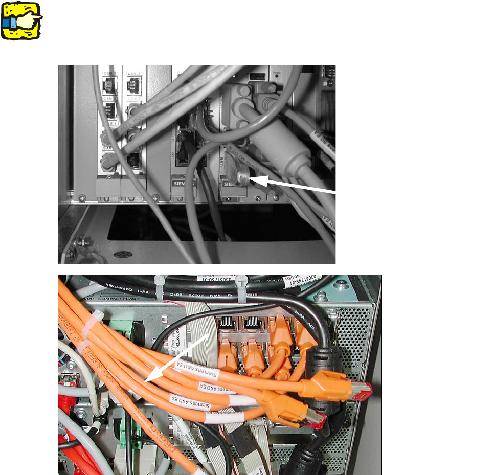
: Plug a USB stick or another suitable storage medium into the USB slot on the station computer.
2
2
: Save the machine data to the storage medium.
: Undock the component trolleys.
: Switch the placement machine off at the main power switch.
USB stick
(computer unit)
USB stick
(box PC)
Head Reconfiguration Kits 2 Assembly Instructions - SIPLACE X-Series Head Reconfiguration Kits
07/2010 Edition
171
2.10.1 Removing the nozzle changer
: To remove the nozzle changer, please read the assembly instructions for the X series nozzle
changer (item no.:00194482-).
2
Risk of a head crash: Always run the placement heads with the appropriate nozzle changer. The
wrong nozzle changer causes a risk of a head crash. 2
2
2
On the subject of the reject bin sensor, also read the assembly instructions for the reject bin sen-
sor, SIPLACE HF series / X series (item no.:00194550-). 2
2.10.2 Removing the nozzle station (description for component trolley docking unit
03015680-06 with 1-wire hub)
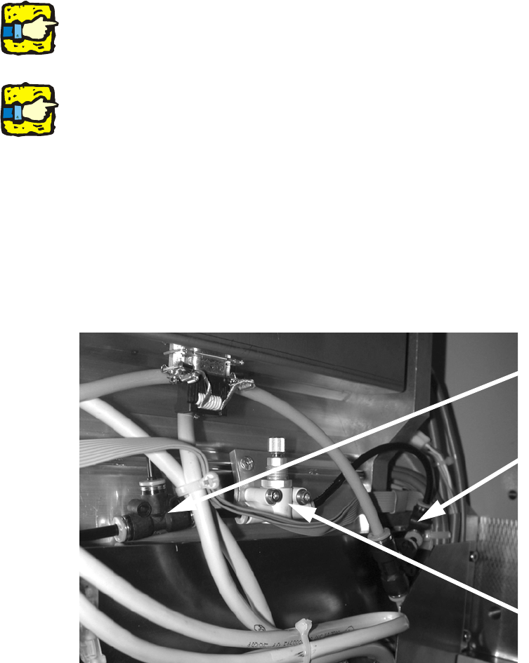
: Disconnect the air supply at the T-piece (see photograph).
: Remove the T-piece for the nozzle station from the component trolley docking unit (see photo-
graph).
: Remove the fine flow restrictor.
2
Disconnect hose from
the T-piece
Remove T-piece for
nozzle station
Remove fine flow
restrictor