182050 User manual.pdf - 第102页
semi automatic 0$&+,1( 352*5$ 00,1* 63&&21),* 85$7,21 1.92 User Manual Software Ve rsion 07SP02 Update on S ta rt-up The windows format cont ains the header dat a which has all the display informa- tion fo …
semi automatic
0$&+,1(352*5$00,1*
63&&21),*85$7,21
Software Version 07SP02 User Manual 1.91
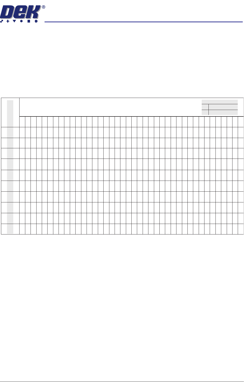
The table below illustrates how the use of the following SPC Configuration
parameters can vary the sampling of SPC Output Parameters from the
machine:
• Data Output Rate
• Start Rate
• Sample Rate
• Start Rate Limit
NOTE
Machine Data and Camera Data are defined in the table in SPC Output
Parameters section.
SPC Data Mode Six modes of data transfer are available as follows:
• None - No SPC data is output at any time.
• Serial + Disc - Outputs data in both modes.
• Serial + Remote - Outputs data in both modes.
• Remote - The data is written to a file called READINGS.DEK located on a
remote network drive.
• Serial - The data is output from the machines serial SPC port.
• Disc - The data is written to a file called READINGS.DEK located on the
machines local drive.
SPC Format All data, irrespective of SPC data mode, is in the selected SPC format, options
are: DOS or Windows.
1 2 3 4 5 6 7 8 9 10111213141516171819202122232425262728293031323334353637383940
Machine Cycles
Start Rate
Sample Rate
Start Rate Limit
Every Cycle
Every Cycle
Every Cycle
Every Cycle
Every Cycle
On Inspect
On Inspect
On Inspect
On Inspect
On Inspect
100
1
00
1510
1510
2510
2510
5120
5
120
1510
15
10
X
X
XXXXXXXXX XXXXXXXXXXXXXXXXXXXXXXXXXX
XX
X
0000000000000000000000000000000000000000
XXXXXXXXXXX XXXXXXXXXXXXXXXXXXXXXXXXXXXXX
00000000000 00000000000000000000000000000
XXXXXXXXXXX XXXXXXXXXXXXXXXXXXXXXXXXXXXXX
00000 0 0 0 0 0 0
XXXXX X X X X X X
00000 0 0 0 0 0 0
XXXXXX
X
XXXXXXXXXXXXXXXXXXXXXXXXXXXXXXXXX
0 0 0 00000000000 0000000000
X X X XXXXXXXXXXX XXXXXXXXXX
0 0 0 00000000000 0000000000
XXXXX X X X
00000 0 0 0
XXXXXXXXXXX XXXXXXXXXXXXXXXXXXXXXXXXXXXXX
00000 0 0 0
XXXXXXXXXX X X X X X X
0000000000 0 0 0 0 0 0
X
XXXXXXXX
X
X XXXXXXXXXXXXX XXXXXXXXXXXXXX
X
0000000000
0
000 0
X
0
Machine DataX
0
Legend
Camera Data

semi automatic
0$&+,1(352*5$00,1*
63&&21),*85$7,21
1.92 User Manual Software Version 07SP02
Update on Start-up The windows format contains the header data which has all the display informa-
tion for the real time plots, including nominals, tolerances and control limits. The
DOS format does not contain this header data. Two options are available as
follows:
• Yes - Use if SPC format is set to DOS, header data is sent on start up.
• No - Use if SPC format is set to windows.
Align Inspect Mode Four modes of alignment inspection are available as follows:
1. None - No fiducial alignment information is output at any time.
2. Pre Print - Board and screen fiducial alignment information is taken after
alignment but before the board is printed.
3. Pre + Post Print - Board and screen fiducial alignment information is taken
before and after the board is printed.
4. Post Print - Board and screen fiducial alignment information is taken after
the board is printed.
The Next and Previous keys are used to move through the parameters.
The Incr. and Decr. keys change the parameter values.
Selecting the Edit Outputs key opens an SPC Output Parameters window and
allows the user to decide which SPC parameters are output to the SPC data file
READINGS.DEK (see the SPC Output Parameters section).
The Edit Limits key opens an Edit SPC Limits window (see the Edit SPC Limits
section), the window gives the operator the ability to set nominal, minimum and
maximum limits for the various SPC parameters and define whether the
machine stops when a limit is exceeded.
semi automatic
0$&+,1(352*5$00,1*
63&&21),*85$7,21
Software Version 07SP02 User Manual 1.93
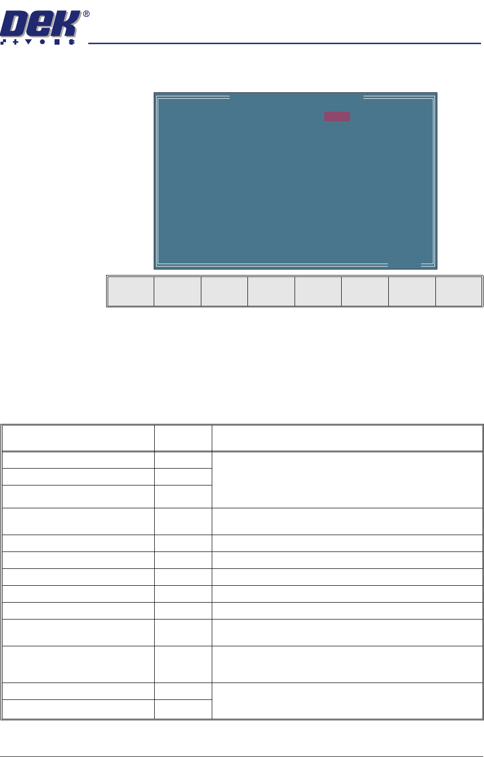
SPC Output
Parameters
Pressing the Edit Outputs key while SPC Configuration Page is displayed
opens the following window and menu bar:
The Next and Previous keys move the cursor vertically through the parameter
list.
The Incr. and Decr. keys switch the setting between YES and NO. If a
parameter is set to YES it is output to the SPC data file (READINGS.DEK).
The Exit key returns to the previous menu.
The SPC Output parameters and their descriptions are listed in the table below:
SPC OUTPUT PARAMETERS
X Alignment Deviation
Y Alignment Deviation
Theta Alignment Deviation
Board Stretch
Front Pressure
Rear Pressure
Separation Speed
Temperature
Relative Humidity
Cycle Time
Table Position
Board Fiducial 1 Score
Screen Fiducial 1 Score
Board Fiducial 2 Score
..more
YES
YES
YES
NO
NO
NO
NO
NO
NO
NO
NO
NO
NO
NO
Next Previous Incr. Decr. Exit
Parameter Parameter
Type
Description
X Alignment Deviation (mm) Camera The residual misalignment of board to stencil obtained by post print
inspection. This data is obtained prior to releasing screen or board
clamps.
Y Alignment Deviation (mm) Camera
Theta Alignment Deviation (arcsec.) Camera
Board Stretch (mm) Camera The calculated stretch of the board relative to the screen. Calcu-
lated from fiducial data obtained by post print inspection.
Front pressure (kg) Machine Average front squeegee print pressure.
Rear Pressure (kg) Machine Average rear squeegee print pressure.
Separation Speed (mm/s) Machine Table Separation speed.
Temperature (deg.C) Machine Not available on this machine.
Relative Humidity (%RH) Machine Not available on this machine.
Cycle Time Machine Time period between the board leaving and returning to the Board
at Left sensor.
Table Position (mm) Machine Values from the last print cycle. This value is the Set Print Height,
which is stored in the machine configuration/calibration file, less the
distance the table has travelled up to the print position.
Board Fiducial n Score Camera For the fiducial outputs nnn will refer to the target score and –mmm
will be the accept score - target score.
Screen Fiducial n Score Camera