182050 User manual.pdf - 第42页
semi automatic 0$&+,1( 352*5$ 00,1* 67$*(' 0 8/7,)/(;7 22/,1* 1.32 User Manual Software Ve rsion 07SP02 5. Using the gri d co-ordinates marked on th e template, posi tion pins which coincid e with gaps be…
semi automatic
0$&+,1(352*5$00,1*
67$*('08/7,)/(;722/,1*
Software Version 07SP02 User Manual 1.31
STAGE 6D - MULTIFLEX TOOLING
WARNING
BOARD CLAMPS. EXTREME CARE MUST BE EXERCISED WHEN WORKING IN
THE TOOLING AREA OF THE MACHINE TO AVOID INJURY. THE FOILS ON THE
FRONT AND REAR BOARD CLAMPS ARE VERY SHARP.
CAUTION
BOARD CLAMPS.
Care must be taken to ensure that the board clamps are
not damaged when removing or replacing tooling.
NOTE
Setting up the MultiFlex tooling is to be performed off the machine.
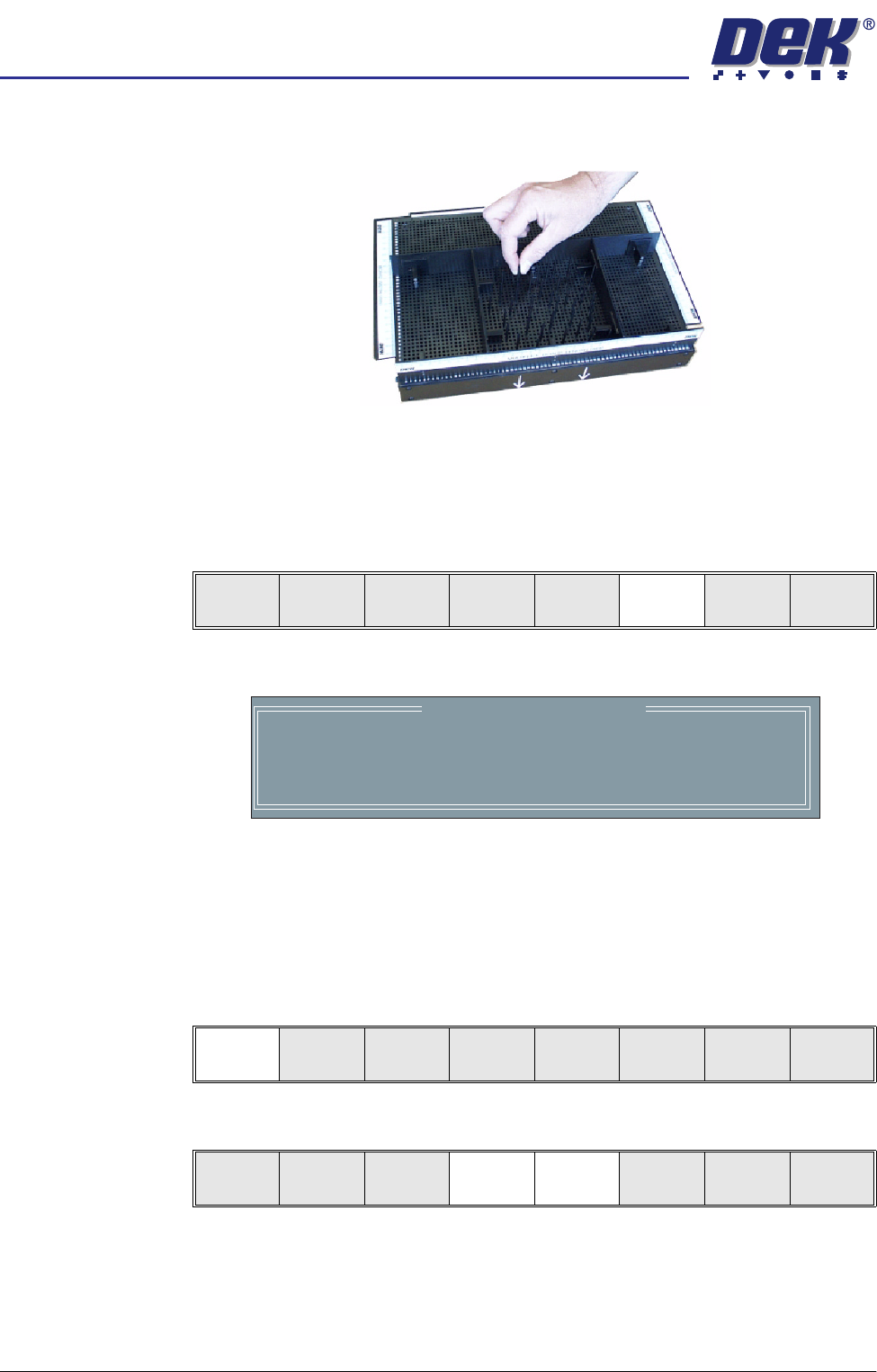
1. Create a box the same size as the board using the side plates.
2. Use the board width and board length dimensions to position the box
correctly.
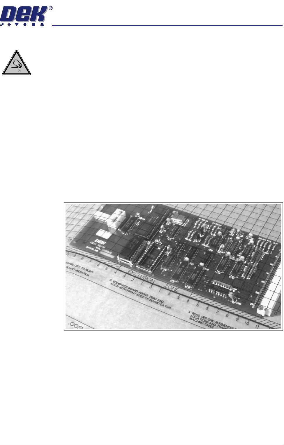
3. Place the PCB on a flat surface, component side up.
4. Position the acetate template, supplied with the tooling, over the PCB such
that the front edge of the board is aligned with the arrow indicators on the
template. Ensure that the centreline of the board is aligned with the template
zero.
semi automatic
0$&+,1(352*5$00,1*
67$*('08/7,)/(;722/,1*
1.32 User Manual Software Version 07SP02
5. Using the grid co-ordinates marked on the template, position pins which
coincide with gaps between the underside board components.
NOTE
Ensure that Generic Tooling is set to Enabled in Set Prefs.
6. If there is a screen loaded return to Stage 5 to remove the screen.
7. Select Change Tooling (F6). The print carriage and the under screen
cleaner are moved to the rear.
The Change Tooling Parameters window is displayed:
8. Setting up the board stop position is automatically done using the board
dimensions previously set in the product file. If they need adjustment to re-
position the board stop for any reason, ie any routing on the board edge or
a badly positioned image on the stencil, this can be done now. If adjustment
is necessary continue with Step 9. If adjustment is not necessary go to Step
14.
9. Select Adjust (F1).
10. Use the Next and Previous keys (F4 - F5) to highlight each parameter.
Mode
Load
Data
Edit
Data
Setup
Squeegee
Change
Screen
Change
Tooling
Change
Language
Exit
Change Tooling Parameters
BOARD WIDTH
BOARD STOP X
BOARD STOP Y
UNDER CLEARANCE
216.0
125.0
142.6
19.0
mm
mm
mm
mm
Adjust
Open
Cover
Home
Cleaner
Board
Stop
Full
Width
Load
Width
Generic
Tooling
Exit
Save Next Previous Incr. Decr. Exit
semi automatic
0$&+,1(352*5$00,1*
67$*('08/7,)/(;722/,1*
Software Version 07SP02 User Manual 1.33
11. Use the Incr. and Decr. keys (F6 - F7), or the forward slash key (/) on the
keyboard, to change the parameter value.
12. Select Save (F2). The message ‘Saving fiducial data - Please wait Board
data file saved’ is displayed.
13. Select Exit (F8).
14. Select Full Width (F5). The message ‘Checking for a board on the belts’
is displayed. Whilst the rear rail is moving the following message ‘Rail
moving...’ is displayed.
15. Select Open Cover (F2).
16. Raise the printhead cover.
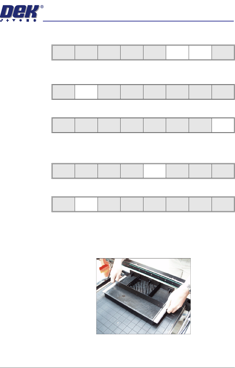
17. The MultiFlex tooling can now be fitted into the appropriate location holes in
the tooling plate. Ensure that the tooling is placed into the correct set of
holes, taking regard of the type of screen being used and hence the position
of the fixed rail.
18. Lower the printhead cover.
19. Press the System button.
Save Next Previous Incr. Decr. Exit
Save Next Previous Incr. Decr. Exit
Save Next Previous Incr. Decr. Exit
Adjust
Open
Cover
Home
Cleaner
Board
Stop
Full
Width
Load
Width
Generic
Tooling
Exit
Adjust
Open
Cover
Home
Cleaner
Board
Stop
Board
Width
Load
Width
Generic
Tooling
Exit