182050 User manual.pdf - 第51页
semi automatic 0$&+,1 (352*5 $00,1 * 67$*( ()2 50)/(; 722/,1* Software Version 07SP02 User Manual 1.41 26. Align the weight s along the centre line in the Y axis and one t hird of the plate length in th e X ax…
semi automatic
0$&+,1(352*5$00,1*
67$*(()250)/(;722/,1*
1.40 User Manual Software Version 07SP02
21. Select Contact Height (F3).
The following window and menu bar is displayed:
22. Select Continue (F1). The message ‘Table at Contact Height. Check
Tooling Clearance’ is displayed.
23. Select Open Cover (F7).
24. Raise the printhead cover.
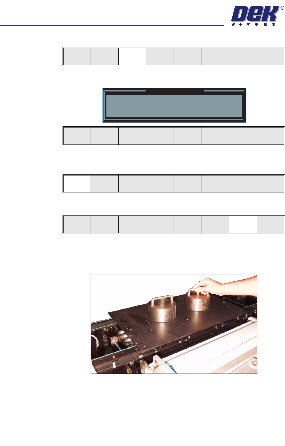
25. Place the FormFlex setup plate centrally over the tooling modules and rails
and place the weights on top of the setup plate.
Contact
Height
Transprt
Height
Change
Screen
Open
Cover
Exit
Contact Height Warning
WARNING Check for obstructions between
the Rails and the Screen
Continue
Open
Cover
Exit
Continue
Open
Cover
Exit
Vision
Height
Open
Cover
Exit
semi automatic
0$&+,1(352*5$00,1*
67$*(()250)/(;722/,1*
Software Version 07SP02 User Manual 1.41
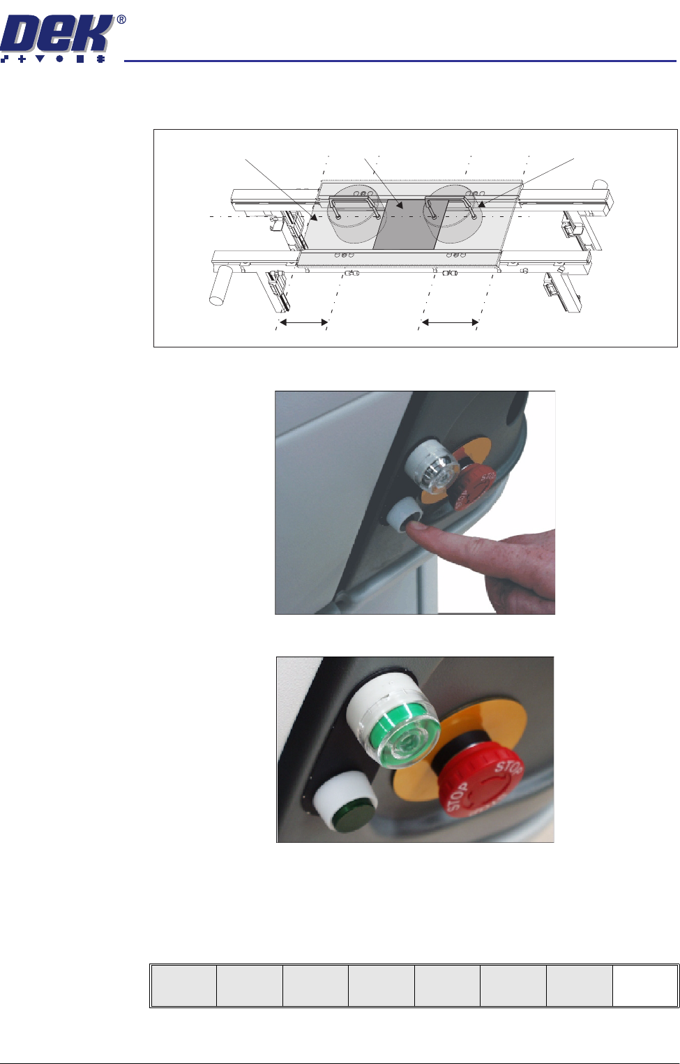
26. Align the weights along the centre line in the Y axis and one third of the plate
length in the X axis.
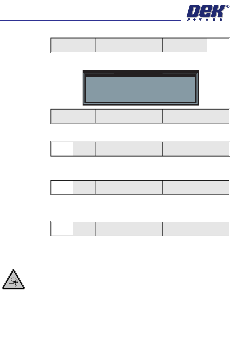
27. Press the operator switch on the front of the machine covers.
28. Wait until the pneumatic indicator on the front cover displays green.
29. Remove the weights and the FormFlex setup plate from the tooling area.
30. Lower the printhead cover.
31. Press the System button.
32. Select Exit (F8).
Board
Setup Plate
Weight (in 2 positions)
C/L
1/3
1/3
Exit
semi automatic
0$&+,1(352*5$00,1*
67$*(()250)/(;722/,1*
1.42 User Manual Software Version 07SP02
33. Select Exit (F8).
The following window and menu bar is displayed:
34. Select Continue (F1).
35. Select Auto Board (F1). The message ‘Board on rails, remove and
continue’ is displayed.
36. Remove the board from the rails.
37. Select Continue (F1).
38. Go to Stage 7.
Universal Set Plate Procedure
WARNING
BOARD CLAMPS. EXTREME CARE MUST BE EXERCISED WHEN WORKING IN
THE TOOLING AREA OF THE MACHINE TO AVOID INJURY. THE FOILS ON THE
FRONT AND REAR BOARD CLAMPS ARE VERY SHARP.
CAUTION
BOARD CLAMPS.
Care must be taken to ensure that the board clamps are
not damaged when removing or replacing tooling.
NOTE
1. Ensure that Generic Tooling is set to Enabled in Set Prefs.
2. When using FormFlex, the print gap in the product file must be set to zero.
1. If there is a screen loaded return to Stage 5 to remove the screen.
Vision
Height
Open
Cover
Exit
Leaving Generic Tooling
WARNING You are about to return
to the Setup Page
Clear all tooling setup
equipment before proceeding
Continue Exit
Continue Exit
Auto
Board
Manual
Board
Continue
Open
Cover